26. AGX Model
agxModel is a library consisting of high level primitives which implement various simulation objects: trees, beams, terrain etc. They are built upon the basic construction elements found in the agxPhysics library: constraints, geometries, bodies and event listeners.
26.1. Granular Fields
A granular field is a physcial quantity computed from discrete granular bodies. For example, in a silo filled with granular material, the mass field for each point in the silo can be computed from the discrete particles. In AGX, fields are diszretized into voxels, each voxel represents one tensor element. Each field element is computed from the particles that intersect the corresponding voxel. A particle can be in several voxels. In that case, a weight proportional to the intersecting volume is calculated.
26.1.1. Basic usage
Computation of any field is done by agxModel::GranularFieldPostProcessor. When creating the post-processor a cuboid volume is placed and discretized into equally sized voxels. This volume defines the boundary of the field. Particles within this boundary contributes to the field, particles outside of it is ignored. The smallest side length of one voxel is not allowed to be smaller than the diameter of the largest granular body. In that case the particle weight calculation will be wrong.
The example below creates a cuboid volume with side length 1.0 that is divided into \(3*3*3 = 27\) voxels.
agx::Physics::GranularBodySystemRef gbs = new agx::Physics::GranularBodySystem();

// Create a granular post-processor
agx::Vec3u shape(3, 3, 3);
agx::Vec3 volume(1.0);
agxModel::GranularFieldPostProcessorRef gpp = new agxModel::GranularFieldPostProcessor(gbs, shape, volume);
After creating the post-processor, add the types of fields it is supposed to compute. Some fields depend on other fields. If such a field is added it will also add the type of field it depends on.
// Add the mass field
gpp->addField(new agxModel::GranularMassField());
The fields are computed by calling gpp->calculateFields(). All the fields added to the post-processor is then computed and saved in the granular field buffers. To access the computed granular field one can do
// Get the pointer to the computed mass field
agx::Real *data = gpp->getField(agxModel::GranularField::MASS)->getFieldData();
26.1.2. Fields
The existing fields are described below.
26.1.2.1. Mass field
The mass field in voxel \(V_{ijk}\) is given by
where \(m_p\) is the mass of particle \(p\) and \(w_p\) is the weight associated with that particle and voxel \(V_{ijk}\).
26.1.2.2. Momentum field
The momentum field in voxel \(V_{ijk}\) is given by
where \(m_p\) is the mass of particle \(p\), \(v_p\) is the velocity of particle \(p\) and \(w_p\) is the weight associated with that particle and voxel \(V_{ijk}\).
26.1.2.3. Velocity field
The velocity field in voxel \(V_{ijk}\) is given by
where \(m_{ijk}\) is the mass field in voxel \({ijk}\) and \(p_{ijk}\) is the momentum-field in voxel \(V_{ijk}\). The velocity field depends on both the mass field and the momentum field.
26.1.2.4. Custom field
It is possible to add custom real buffers to the GranularBodySystem. Using these buffers it is possible to calculate a custom field. For example, if each particle is assigned an unique concentration value using a custom buffer. One can then use this custom buffer to calculate a concentration field. It is important that the custom field get the name of the custom buffer.
agx::Physics::GranularBodySystemRef gbs = new agx::Physics::GranularBodySystem();
gbs->addCustomBufferReal("concentration");

// ....

// Create a granular post-processor
agx::Vec3u shape(3, 3, 3);
agx::Vec3 volume(1.0);
agxModel::GranularFieldPostProcessorRef gpp = new agxModel::GranularFieldPostProcessor(gbs, shape, volume);

// Add the custom buffer field. Use the same name ass the previously created buffer.
gpp->addField(new agxModel::GranularCustomBufferField("concentration"));
The custom field in voxel \(V_{ijk}\) is given by
where \(c_p\) is the custom buffer value for particle \(p\) and \(w_p\) is the weight for particle \(p\) in voxel \(ijk\).
26.2. SuctionGripper
The general idea of the agxModel::SuctionGripper is to model a gripper tool for robotics,
where one or more agxModel::SuctionCup s are powered by a agxModel::VacuumSystem.
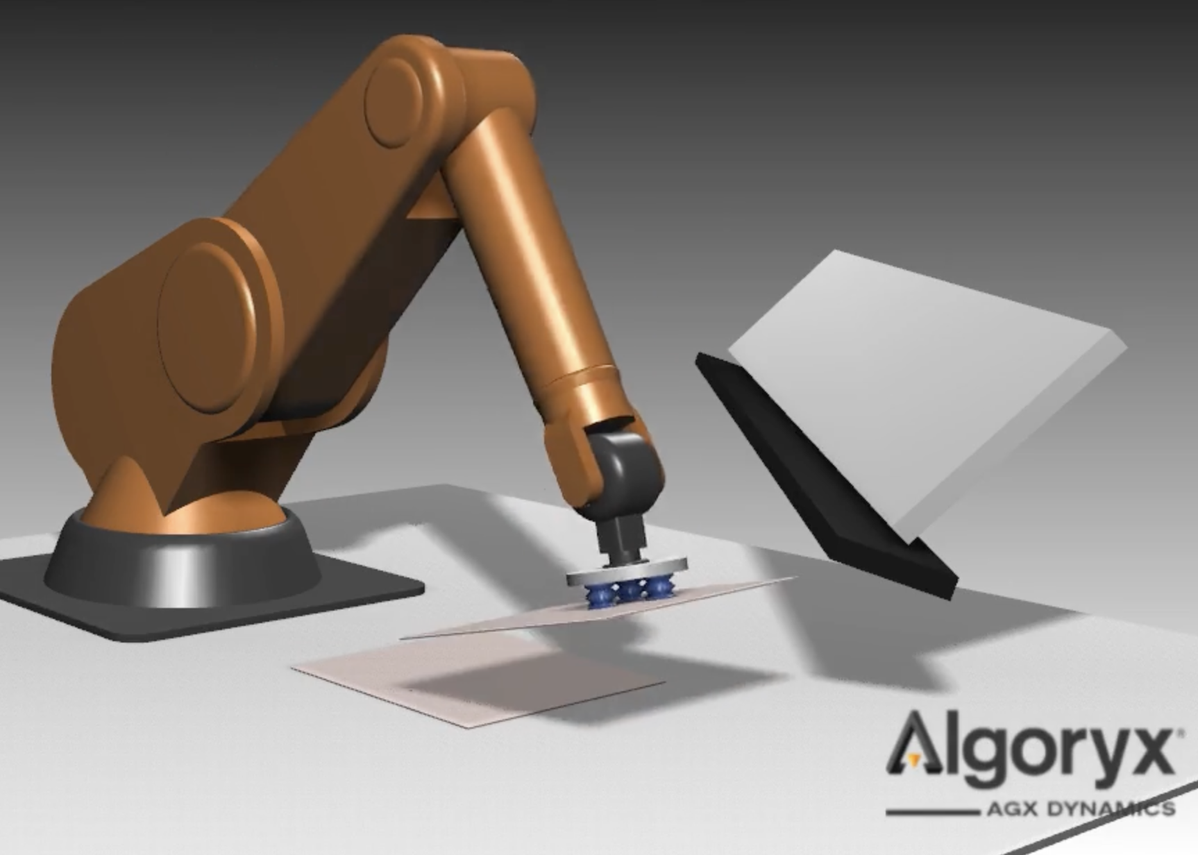
Fig. 26.1 Image capture from data/python/tutorials/tutorial_custom_suction_gripper.agxPy
The agxModel::SuctionGripper is based on the agxSDK::Assembly class which makes it possible
to model the relative suction cup positions in a local coordinate system.
The SuctionGripper requires a internal holder rigid body to be set. Its purpose is for mounting suction cups and for connecting the gripper to, for example, a robot.
// Create SuctionGripper
agxModel::SuctionGripperRef suctionGripper = new agxModel::SuctionGripper();
// Create holder rigid body, which suction cups should be attached to
agx::RigidBodyRef holderBody = new agx::RigidBody("MyHolderBody");
suctionGripper->setHolderRigidBody(holderBody);
The heart of the SuctionGripper implementation lies in the collision detection handling for each individual suction cup and their one or more sensors. Each cup interaction will generate SuctionCupInteraction’s which include information for a VacuumSystem algorithm to base its vacuum force distribution.
It is possible to inherit from the agxModel::VacuumSystem, agxModel::SuctionCup
or the agxModel::SuctionCupInteraction to customize the default behaviour.
class MyVacuumSystem : public agxModel::VacuumSystem {
  // ..
};
// Replace VacuumSystem
suctionGripper->setVacuumSystem(new MyVacuumSystem());
26.2.1. Vacuum System
The purpose of the vacuum system is to maintain a desired vacuum for all SuctionCup’s for one SuctionGripper. The desired vacuum level is set:
// Create vacuum system with desired vacuum level at 20% vacuum (80% of atmospheric pressure)
agx::Real desiredVacuum = agx::Real(0.2)
agxModel::VacuumSystemRef vacuumSystem = new agxModel::VacuumSystem(desiredVacuum);
// The desired vacuum can't be >= 1 (100% is perfect vacuum)
vacuumSystem->setDesiredVacuum(agx::Real(0.4));
The internal state for the VacuumSystem can be tuned in the following way:
// Disable the pump (enabled by default).
vacuumSystem->setEnablePump(false);

// Set the outside pressure in Pascal (atmospheric pressure by default)
agx::Real pressureOnMars = agx::Real(610);
vacuumSystem->setOutsidePressure(pressureOnMars);

// Set the outside gas density (by default set to 1.225 [kg / m^3])
agx::Real gasDensityOnMars = agx::Real(0.02);
vacuumSystem->setOutsideGasDensity(gasDensityOnMars);
For a custom VacuumSystem there are two virtual functions to consider implementing.
// This virtual function is responsible for calculating the actual force a suction cup can apply to objects, given the current situation.
// Could consider for example current leakage near the cup.
virtual agx::Real MyVacuumSystem::calculateAvailableVacuumForce(agxModel::SuctionCup* cup) override {

// This virtual function for updating the vacuum system.
// Which allow for a dynamic vacuum system.
// The default system however will toggle between desired vacuum and zero vacuum, depending on if the pump is enabled.
virtual void MyVacuumSystem::step(const agx::Real& dt, const SuctionGripper* gripper) override {
26.2.2. Suction Cup Interaction
The data contained in a SuctionCupInteraction is only valid throughout the time step. The after the collision detection stage in AGX one SuctionCupInteraction is activated for each rigid body the suction cup sensors has collided with. The API available for the suction cup interactions are the following:
// Directly after the collision detection we can go through the active interactions of one suction cup
for( auto interaction : cup->getActiveInteractionsVector() ) {

  // Interacting rigid body which will be affected by the vacuum force.
  agx::RigidBody* rigidBody = interaction->getRigidBody();

  // How many seal sensors the rigid body is interacting with
  size_t sealCount = interaction->getSealCount();

  // True if the object collides with the line sensor, located along the suction cup normal.
  bool centered = interaction->getCentered();

  // The distance to the closest point on the colliding rigid body along the center vector.
  agx::Real centerDistance = interaction->getCenterDistance();

  // The surface normal at the closest point of the colliding rigid body.
  agx::Vec3 surfaceNormal = interaction->getCenterNormalWorld();

  // The world position where the vacuum force will apply a wrench.
  agx::Vec3 worldForcePosition = interaction->getFoundSurfacePositionWorld();
}
After AGX has stepped the DynamicsSystem, forces and velocities are updated, and the following API calls are valid for examining the state of the interaction
// Directly after the collision detection we can go through the active interactions of one suction cup
for( auto interaction : cup->getActiveInteractionsVector() ) {

    // Last scalar vacuum force applied to the rigid body of the interaction
    agx::Real lastScalarForce = interaction->getCalculatedScalarForce();

    // Last directional vacuum force applied to the rigid body of the interaction
    agx::Vec3 lastDirectionalForce = interaction->getCalculatedForce();

    // Sum of all friction forces between the suction cup and the rigid body
    agx::Vec3 lastFrictionForce = interaction->getCurrentFrictionForce();

    // The total normal force between the suction cup and the rigid body
    agx::Vec3 normalForce = interaction->getCurrentContactNormalForce() const;

    // The maximal relative velocity between the suction cup and the rigid body considering all contact points.
    agx::Real relativeVelocity = interaction->getCurrentRelativeVelocity();
}
For a custom SuctionCupInteraction there is one virtual function to consider implementing.
class MySuctionCupInteraction : public agxModel::SuctionCupInteraction {
  // ..
};
// Virtual function responsible for updating the actual forces to apply to the interacting rigid body
// by calling this->setCalculatedScalarForce() and this->setCalculatedForce()
virtual agx::Real MySuctionCupInteraction::updateVacuumForce(const SuctionCup* cup, const VacuumSystem* vacuumSystem, const agx::Real& fraction) override {
26.2.3. Suction Cup
The SuctionCup require one rigid body to be valid. The SuctionCup comes with built in handling of two types of sensors, seal (Spheres) and Line. The purpose of the sensors are to detect nearby geometries of dynamic rigid bodies and create SuctionCupInteraction’s to contain all important information for vacuum forces to be computed.
The Line sensor is attached to each suction cup by default. The suction cup can be equipped with seal sensors, which help detecting if the interaction is sealed or not and will help defining a leakage area. It is up to the ::calculateAvailableVacuumForce function of the vacuum system to consider using a leakage area or not.
The local x-y plane for the suction cup rigid body define the suction cup plane. If seal sensors are used these are placed in this plane at lipRadius distance from the body origin. It is expected that the user constrains the cup body to the holder body, but it is not forced in any way.
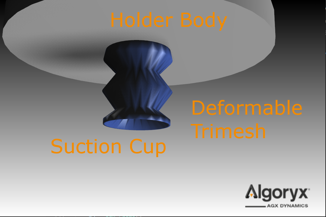
Fig. 26.2 The suction cup attached to the holder
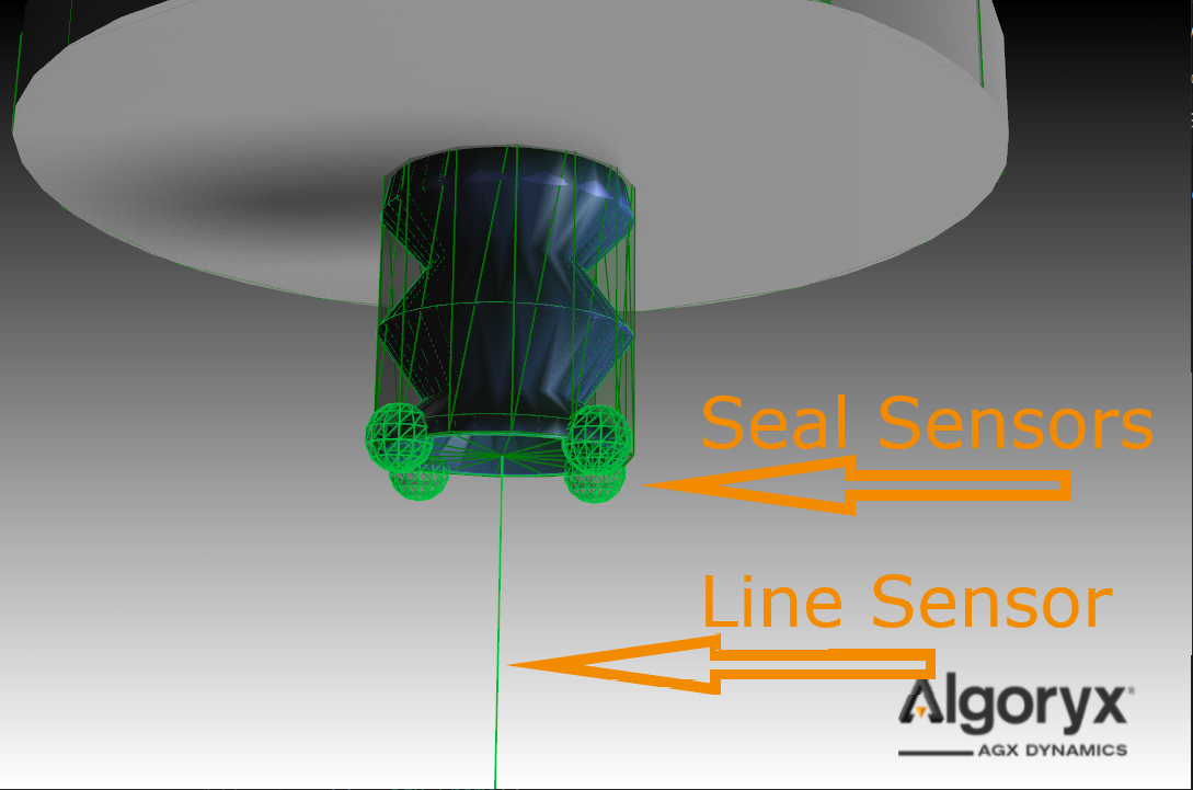
Fig. 26.3 Four seal sensors positioned in the suction cup local plane, at lip radius distance from the center.
If no rigid body is added to the constructor, a default rigid body is created.
The default rigid body will get a cylindrical collision geometry using the lipRadius and lipHeight for dimensions.
All suction cup rigid bodies will by default be given a agxCollide::Line shape geometry sensor.
There are multiple ways to customize the suction cup on creation:
// Go with the default body
agx::RigidBody* cupBody = nullptr;
// Lip radius, which define the area for the cup interaction, and therefore the maximum vacuum force
agx::Real lipRadius = agx::Real(0.025);
// Lip height, the height of the default collision geometry.
agx::Real lipHeight = agx::Real(0.01);
// How many spherical sensors you like on the circumference of the lip.
size_t sealResolution = size_t(4);
// Reach of the line sensor
agx::Vec3 lineSensorVector = agx::Vec3(0,0,-0.1);
// Radius of the seal senors spheres
agx::Real sealSensorReach = agx::Real(0.01);
agxModel::SuctionCupRef cup = SuctionCup( cupBody, lipRadius, lipHeight, sealResolution, lineSensorVector, sealSensorReach);
There is one variable to customize during runtime:
// Define a mounting radius > 0, defaults to half of the lip radius
// Will effect the pressure drop at the lip when the lip is not sealed.
agx::Real mountingRadius = 0.01;
cup->setMountingRadius(mountingRadius);
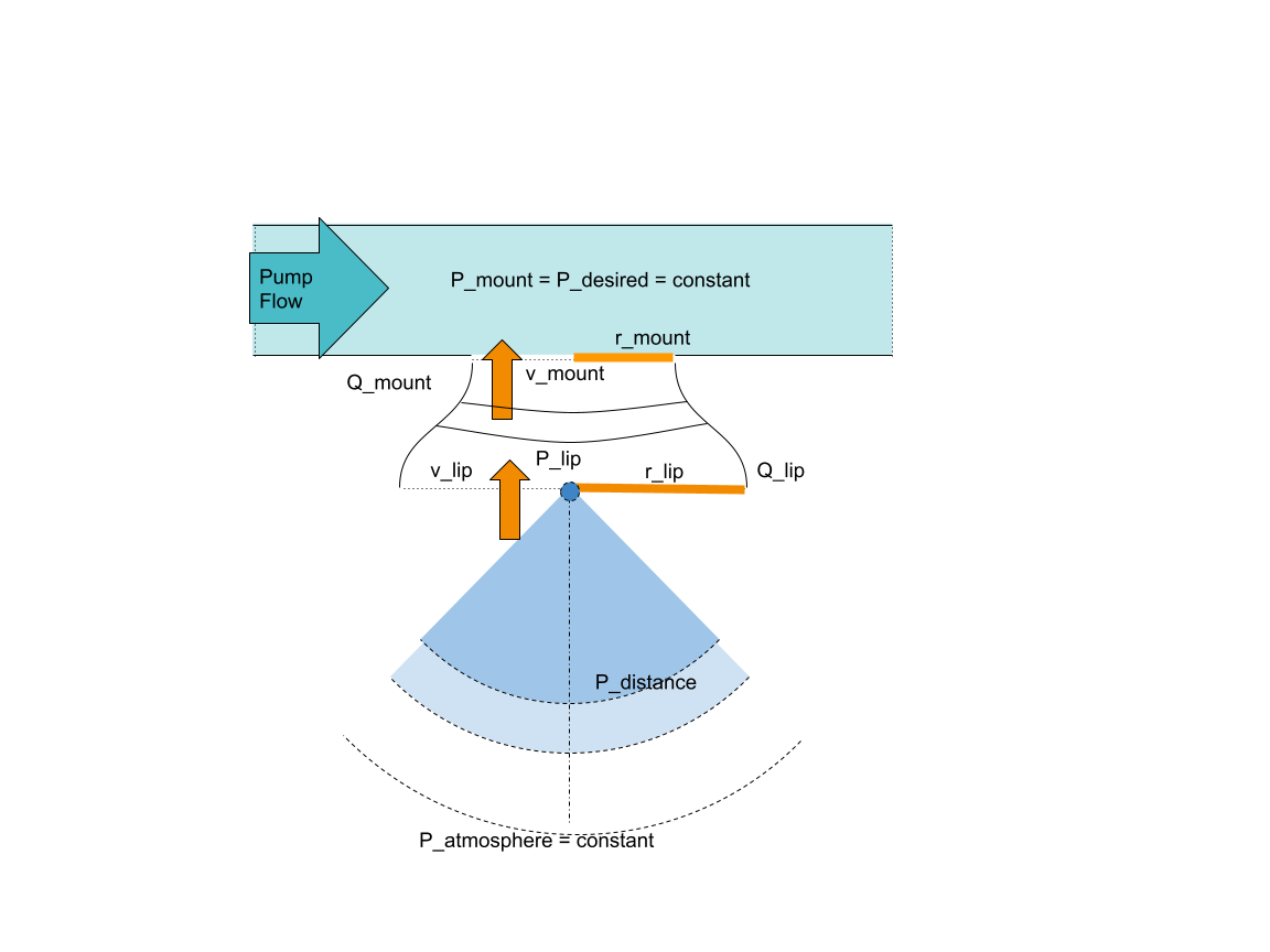
Fig. 26.4 Describe the vacuum system and how the pressure at the lip and nearby is modeled.
The default Vacuum system model a constant vacuum at the mount. The pressure at the lip \(P_l\) when there is leakage dropps according to Bernoulli’s principle, assuming constant flow \(Q_{l} = Q_{m}\) and zero air speed far away from the lip.
We define the velocity relation between the air speed at the mount \(v_m\) and the air speed at the lip \(v_l\).
We find the air velociy at the mount from Bernoulli’s principle given the pressure at the mount \(P_m\), air density \(\rho_{air}\), atmospheric pressure \(P_a\) and assuming zero air velocity far away from the cup.
Pressure drop at the lip then comes from the calculated air speed at the lip:
The pressure gradient decay quadratically relative to the distance from the suction cup center. This from assuming the flow is constant at every imaginary half sphere away from the cup. The forces due to vacuum will be applied to the objects identified by the cup sensors as well as an opposite reaction force will be applied to the cup.
26.3. Tree
agxModel::Tree is a structure of Branch objects in a mathematical Tree structure where a Branch can have several child branches. Even though the class is to save a tree structure, it can be used to create a simulation of an actual tree. To use it for such things, it requires you to create your own geometries and add them to the tree structure. Tree holds functions to cut, split and in other ways change the Tree structure.
// Create a tree
agxModel::TreeRef tree = new agxModel::Tree();
A newly created Tree will be empty except for its root. The root is the base branch of the tree. It can be accessed as:
agxModel::Tree::BranchRef treeRoot = tree->getRoot();
To create a new branch, to attach to the root, we need to know how it should be rotated and where it should be attached. The easiest way to do this is to decide a start and end position of the branch. Note that the end position is only used to decide in which direction the branch should point. It is also possible to just set a transform of the branch and send it in as you create it. When the branch is created it is possible to attach it to another branch, which will then make the new branch a child to that one.
// Create new branch
agxModel::Tree::BranchRef newBranch = new agxModel::Tree::Branch(startPosition, endPosition);
// or
agxModel::Tree::BranchRef newBranch = new agxModel::Tree::Branch(transform);

// Attach new branch
branch->addBranch(newBranch);
When the branch is created, it will create a rigid body, but it has no geometries. To represent the branch it is possible to use any geometry, but only capsules and cylinders fully support all functionalities for branches by default. By doing branch->getRigidBody() we can get the rigid body connected to the branch. The body will be placed and rotated as specified when we created the branch. Adding geometries to the branch is done by simply adding them to the rigid body, as you would normally do.
There are a few different things we can do with a tree. One useful function makeStatic, which can be used to make all the rigid bodies in the tree static, and remove all constraints from the simulation.
tree->makeStatic(true);
The boolean set to true enables the tree to wake up when exposed to a contact. By default, any contact can wake it up, but if you want to specify this more explicitly, an agxModel::Tree::TreeExecuteFilter can be set when calling makeStatic.
The tree will keep being dynamic after the contact, so if you want it to go back to being static, makeStatic must be called again. A static tree can also be made dynamic doing:
tree->makeDynamic();
Another feature of agxModel::Tree is the possibility to cut branches off in an easy way. Cutting a branch means that the constraint holding the given branch to the tree is removed and the branch that is cut off will be the root of a new tree, where all its child branches are part of it. There are two ways to cut a branch.
agxModel::TreeRef newTree = tree->cut(branch);
// or
agxModel::TreeRef newTree = tree->cut(branchGeometry, point, minShapeHeight);
cut(branch) will cut it off at the start of the branch. cut(branchGeometry, point, minShapeHeight) can be used to cut a branch in the middle of it, or in any point of the given geometry. minShapeHeight sets the limit for how small a geometry segment can become. If a cut would resolve in a geometry shorter than minShapeHeight, the cut is instead made between two geometries or directly at a branch connection. By default cutting a branch geometry in the middle is however only supported by capsules and cylinders. Note that cut assumes that the geometries in a branch are ordered in position with first geometry furthest down in branch body coordinates.
To handle certain events that can happen to a tree, it is possible to use a BranchEventListener. This is a class that contains a few methods that you can implement. By default, they will do nothing. It contains; onCreate, onHightLoad and clone. onCreate is called when the branch has been added to the simulation and when it has been configured with position, orientation and constraint to parent (if present). onHighLoad is called when a branch has a load applied to it that exceeds the set limit value. By default a branch is infinitely strong, so to reach the limit, a lower value must be set manually. There are two parts to this limit, one for the tensile strength and one for the bending strength.
// Set the limit values for load on a branch
branch->setMaxLoad(tensileStrength, bendingStrength);
// or
branch->setMaxTranslationalLoad(tensileStrength);
branch->setMaxRotationalLoad(bendingStrength);