27. AGX Model: Deformable Beam
Deformable beam is a lumped element model where the bulk properties of a beam is defined given choices of Beam Model, Beam Model Properties and the length of the beam. The lumped element model is independent of resolution (number of elements) of the beam.
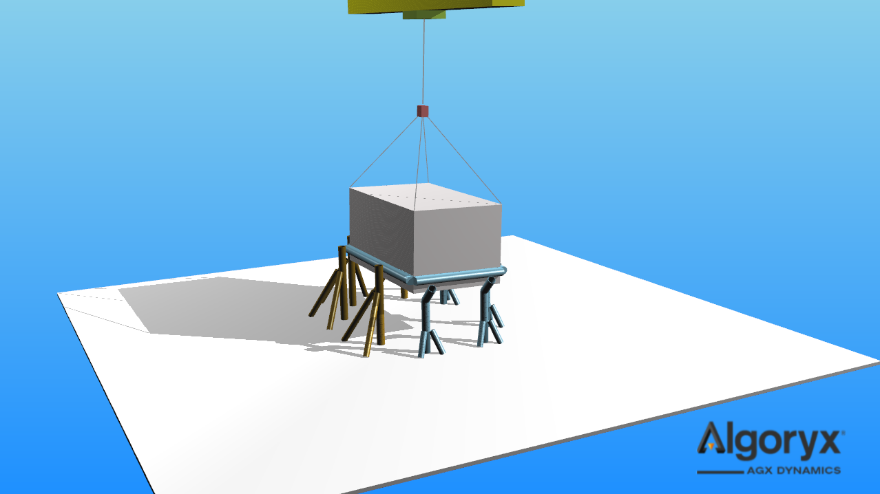
Fig. 27.1 Traverse crane placing heavy load with the help of Hollow Circular Beam model guide beams.
27.1. Beam Model
The beam model (agxModel::BeamModel) is the base class of numerous implementations and is describing
the geometry and bulk properties - such as stretching, bending and torsion - of beams. Each beam model implementation
contains immutable parameters describing the profile/cross section and is responsible for calculating the cross section
area, moment of inertia (second moment of area and polar moment) and creating the template geometry used in each
segment rigid body of the beam the model is associated with.
A beam model instance may be shared with an arbitrary number of Beam instances.
agxModel::CircularBeamRef circularModel_r05 = new agxModel::CircularBeam( /* radius */ 0.05 );
agxModel::BeamRefVector beams;
for ( size_t i = 0; i < 20; ++i )
  beams.push_back( new agxModel::Beam( /* model */ circularBeam_05,
                                       /* resolution */ 2 * (i + 1),
                                       /* length */ 3.0 ) );
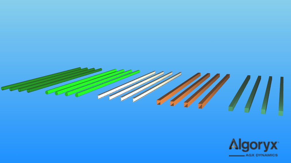
Fig. 27.2 Beams with various (10, 15, 20 and 25 elements) resolutions and models. The beam models, from left to right: Hollow Circular Beam, Circular Beam, I-Beam, Hollow Rectangular Beam and Rectangular Beam.
27.1.1. Beam Model Properties
Beam model properties (agxModel::BeamModelProperties) carries bulk material parameters such as Young’s Modulus,
Poisson’s Ratio and Damping Time. These parameters are translated to compliance and damping in the constraints between
beam segments, which also depends on the beam model (cross section area, moment of inertia) and resolution of the beam.
Property |
Default |
|---|---|
Young’s Modulus |
200.0E9 |
Poisson’s Ratio |
0.3333 |
Damping Time |
0.03333 |
The density, which affects the mass properties of the beam, is taken from the (agx::Material) material
instance associated to the beam. The mass properties of the beam is calculated when the beam is being initialized or when
the material is being assigned, i.e., changing density in an already assigned material of an already initialized beam won’t
affect the mass properties of the beam.
Young’s Modulus, Poisson’s Ratio and Damping Time are synchronized in the associated beams several times per time step but the propagation (to the constraints in a beam) isn’t instant, but are guaranteed to be used the next time the beam is being solved.
Note
Damping Time: For real-time simulations, i.e., time step size >> 0 ~ 0.01, there is no correlation between the material properties of a beam and the damping time parameter. If the time step size is decreased close to the true damping time of the simulated material, it’s possible to map the damping time parameter to the viscosity of the material. For real-time simulations it’s important that the damping time parameter is larger than the time step, typically two times the time step size, for unconditionally stable simulations.
A beam model properties instance may be shared with an arbitrary number of Beam Model instances, and a beam model will always contain a valid reference to a beam model properties instance.
agx::MaterialRef steelBeamMaterial = new agx::Material( "steel" );
steelBeamMaterial->getBulkMaterial()->setDensity( 7400.0 );

agxModel::BeamModelPropertiesRef steelBeamProperties = new agxModel::BeamModelProperties();
steelBeamProperties->setYoungsModulus( 210.0E9 );
steelBeamProperties->setPoissonsRatio( 0.31 );

agxModel::CircularBeamRef circularModel1 = new agxModel::CircularBeam( /* radius */ 0.1 );
circularBeam1->setProperties( steelBeamProperties );

agxModel::CircularBeamRef circularModel2 = new agxModel::CircularBeam( /* radius */ 0.12,
                                                                       /* properties */ steelBeamProperties );

agxModel::CircularBeamRef circularModel3 = new agxModel::CircularBeam( /* radius */ 0.12 );
circularModel3->getProperties()->setYoungsModulus( steelBeamProperties->getYoungsModulus() );
circularModel3->getProperties()->setPoissonsRatio( steelBeamProperties->getPoissonsRatio() );
In the example above, all three models has identical bulk properties but circularModel1 and circularModel2 shares
the steelBeamProperties instance, so when any value is updated in steelBeamProperties, all beams based on
circularModel1 and circularModel2 will have changed bulk properties while circularModel3 will have the old
values when it was assigned copies of the parameters.
27.1.2. Rectangular Beam
Rectangular cross section beam model constructed given width and height. The geometry in each beam segment
contains a single agxCollide::Box of size \(\left(0.5 h, 0.5 w, 0.5 \Delta L\right)\) where
\(\Delta L\) is determined by the resolution and length of the Beam this model is part of.
agxModel::RectangularBeamRef
   rectangularModel = new agxModel::RectangularBeam( /* width */ 0.05,
                                                     /* height */ 0.10 );
rectangular_model = agxModel.RectangularBeam(width = 0.05,
                                             height = 0.10)
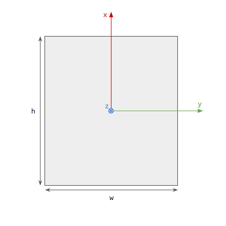
Fig. 27.3 Rectangular cross section defined by width (w) and height (h).
Moment of inertia:
The polar moment \(J\) is an approximation that’s more accurate than \(J = I_{xx} + I_{yy}\). See Moment Of Inertia Scale for more information how to tune the accuracy even further.
Cross section area:
27.1.3. Hollow Rectangular Beam
Hollow rectangular cross section beam model constructed given width, height and thickness. The geometry in each beam segment
contains four agxCollide::Box instances of sizes - bottom and top flange \(\left(0.5 t, 0.5 w, 0.5 \Delta L\right)\),
left and right web \(\left(0.5 h_i, 0.5 t, 0.5 \Delta L\right)\) - where \(\Delta L\) is determined by the resolution and
length of the Beam this model is part of.
agxModel::HollowRectangularBeamRef
   hollowRectangularModel = new agxModel::HollowRectangularBeam( /* width */ 0.12,
                                                                 /* height */ 0.15,
                                                                 /* thickness */ 4.0E-3 );
hollow_rectangular_model = agxModel.HollowRectangularBeam(width = 0.12,
                                                          height = 0.15,
                                                          thickness = 4.0E-3)
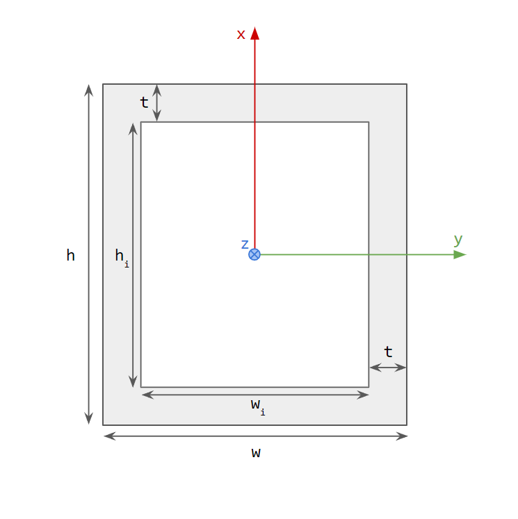
Fig. 27.4 Hollow rectangular cross section defined by width (w), height (h) and thickness (t).
Moment of inertia:
The used polar moment \(J = I_{xx} + I_{yy}\) is not very accurate but given specific sizes and data it’s possible to tune this model using Moment Of Inertia Scale.
Cross section area:
27.1.4. Circular Beam
Circular cross section beam model constructed given radius. The geometry in each beam segment contains a single agxCollide::Cylinder
of size \(\left(r, \Delta L\right)\) where \(\Delta L\) is determined by the resolution and length of the Beam this
model is part of.
agxModel::CircularBeamRef
   circularModel = new agxModel::CircularBeam( /* radius */ 0.05 );
circular_model = agxModel.CircularBeam(radius = 0.05)
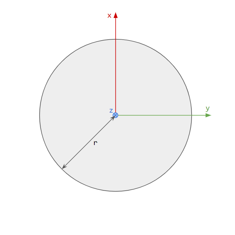
Fig. 27.5 Circular cross section defined by radius (r).
Moment of inertia:
Cross section area:
27.1.5. Hollow Circular Beam
Hollow circular cross section beam model constructed given radius and thickness. The geometry in each beam segment contains a single
agxCollide::HollowCylinder of size \(\left(r_i, \Delta L, t\right)\) where \(\Delta L\) is determined by the resolution
and length of the Beam this model is part of.
agxModel::HollowCircularBeamRef
   hollowCircularModel = new agxModel::HollowCircularBeam( /* radius */ 0.07,
                                                           /* thickness */ 3.0E-3 );
hollow_circular_model = agxModel.CircularBeam(radius = 0.07,
                                              thickness = 3.0E-3)
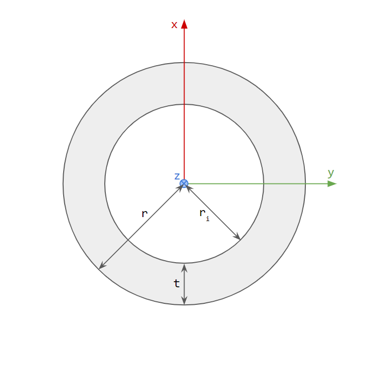
Fig. 27.6 Hollow circular cross section defined by radius (r) and thickness (t).
Moment of inertia:
Cross section area:
27.1.6. I-Beam
I cross section beam model constructed given width, height, flange and web thickness. The geometry in each beam segment contains
three agxCollide::Box instances if sizes - bottom and top flange \(\left(0.5 t_f, 0.5 w, 0.5 \Delta L\right)\) and the web
\(\left(0.5 h_w, 0.5 t_w, 0.5 \Delta L\right)\) - where \(\Delta L\) is determined by the resolution and length of the
Beam this model is part of.
agxModel::IBeamRef
   iModel = agxModel::IBeam( /* width */ 0.15,
                             /* height */ 0.17,
                             /* flangeThickness */ 4.0E-3,
                             /* webThickness */ 5.5E-3 );
i_model = agxModel.IBeam(width = 0.15,
                         height = 0.17,
                         flangeThickness = 4.0E-3,
                         webThickness = 5.5E-3)
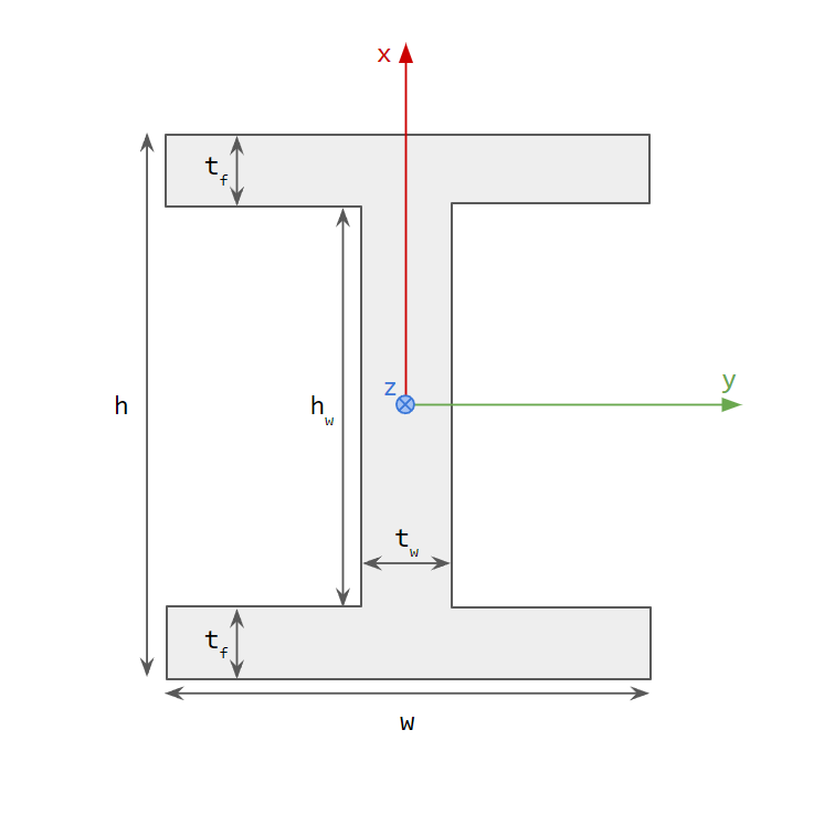
Fig. 27.7 I cross section defined by width (w), height (h), flange thickness (\(t_f\)) and web thickness (\(t_w\)).
Moment of inertia:
The used polar moment \(J = I_{xx} + I_{yy}\) is not very accurate but given specific sizes and data it’s possible to tune this model using Moment Of Inertia Scale.
Cross section area:
27.1.7. Moment Of Inertia Scale
The Beam Model base class carries a moment of inertia scale, default (1, 1, 1), that scales the moment of inertia implemented by the model. This enables models, of non-circular cross sections (Rectangular Beam, Hollow Rectangular Beam, I-Beam), of a given size, to be tuned against validated data. This is mostly relevant for the polar moment \(J\), related to the target torsion angle given external forces and torques applied to the beam.
Note
agxModel::BeamModel::getMomentOfInertia() returns the scaled moment of inertia and should be used in most cases. The
moment of inertia of a model is implemented in agxModel::BeamModel::calculateMomentOfInertia() which returns the
unscaled, model specific implementation of the moment of inertia.
For example, if the polar moment is know for a given model and sizes, e.g., J = 1.234E-5, set the scale as:
const auto J = 1.234E-5;
const auto polarScale = J / model->calculateMomentOfInertia().z();
model->setPolarMomentOfInertiaScale( polarScale );
which will result in the final polar moment to be the known J.
27.2. Beam
A beam is constructed given a Beam Model, number of elements and length. The beam segments, i.e., bodies, geometries and
constraints, are created when initialize() is called or when the beam is added to a simulation.
agxModel::RectangularBeamRef model = new agxModel::RectangularBeam( 0.15, 0.15 );

agxModel::BeamRef beam1 = new agxModel::Beam( model, 15u, 5.0 );
// Explicit initialization.
if ( !beam1->initialize() )
  std::cerr << "beam1 initialization failed!" << std::endl;
else
  simulation->add( beam1 );

agxModel::BeamRef beam2 = new agxModel::Beam( model, 25u, 3.0 );
// Implicit initialization.
simulation->add( beam2 );
if ( !beam->isInitialized() ) {
  std::cerr << "beam2 initialization failed!" << std::endl;
  simulation->remove( beam2 );
}
See Beam Frame for information where the segments are created and transformed, and Creating Beams for different ways to create, initialize and transform beams.
27.2.1. Beam Frame
The beam frame is the frame in which all beam segments lives in. All segment rigid bodies are inheriting this frame, but the beam frame is static so it won’t move with the beam during a simulation, it’s mostly used for the initial transform.
The beam frame is defined by:
The forward direction, the direction along the beam, is by definition the +z axis (inherited from constraints and the constraint axis).
The up direction is chosen to be the +x axis (+x or -x are the choices and +x feels more natural).
The right direction becomes the +y axis.
The start position of the first segment is located at the origin in the beam frame.
For a given beam length \(L\), the end position of the last segment is located at \(\left(0, 0, L\right)\) in the beam frame.
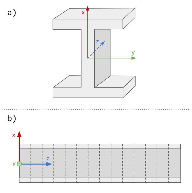
Fig. 27.8 a) Beam segment (rigid body) frame at any location along the beam with up along +x, right along +y and forward along +z (into the screen). b) Beam frame instantly after the beam has been initialized with up along +x, right along +y (out of the screen) and forward along +z.
Note
The beam frame (initially), beam segments (rigid bodies) frames and beam constraints frames coincides.
27.2.2. Creating Beams
There are several ways to create and initialize beams. The default transform will coincide with the world frame where the beam segments are created along world +z axis with up axis along world +x and right axis along world +y.
// 5 m long beam with 5 segments (results in 1 m each).
agxModel::BeamRef beam = new agxModel::Beam( new agxModel::CircularBeam( 0.1 ),
                                             5u,
                                             5.0 );
beam->initialize();
for ( const auto segment : beam->getSegments() )
  // segment->getBeginPosition() == segment->getRigidBody()->getPosition()
  std::cout << segment->getBeginPosition() << std::endl;
std::cout << "End: " << beam->getEndPosition() << std::endl;
[0.0, 0.0, 0.0]
[0.0, 0.0, 1.0]
[0.0, 0.0, 2.0]
[0.0, 0.0, 3.0]
[0.0, 0.0, 4.0]
End: [0.0, 0.0, 5.0]
27.2.2.1. Set Rotation
Beam rotations can be calculated using the static method agxModel::Beam::calculateRotation, taking desired forward direction of
a beam in world coordinate frame and world up (default world +z axis) direction. The world up is a hint of the direction the up (x)
axis of the beam should align with. The following example is creating the beams along the world x axis, but world up is alternated (z, y, x + y).
agxModel::IBeamRef model = new agxModel::IBeam( 0.15, 0.20, 0.01, 0.015 );
const auto beamForwardWorld = agx::Vec3::X_AXIS();

agxModel::BeamRef beam1 = new agxModel::Beam( model, 5u, 5.0 );
beam1->setRotation( agxModel::Beam::calculateRotation( /* forward */ beamForwardWorld,
                                                       /* worldUp */ agx::Vec3::Z_AXIS() ) );
// The is the start position, in world, of beam1.
beam1->setPosition( 0, 1.5, 0 );
simulation->add( beam1 );

agxModel::BeamRef beam2 = new agxModel::Beam( model, 5u, 5.0 );
beam2->setRotation( agxModel::Beam::calculateRotation( /* forward */ beamForwardWorld,
                                                       /* worldUp */ agx::Vec3::Y_AXIS() ) );
// The is the start position, in world, of beam2.
beam2->setPosition( 0, 0.5, 0 );
simulation->add( beam2 );

agxModel::BeamRef beam3 = new agxModel::Beam( model, 5u, 5.0 );
beam3->setRotation( agxModel::Beam::calculateRotation( /* forward */ beamForwardWorld,
                                                       /* worldUp */ agx::Vec3::Y_AXIS() +
                                                                     agx::Vec3::Z_AXIS() ) );
// The is the start position, in world, of beam3.
beam3->setPosition( 0, -0.5, 0 );
simulation->add( beam3 );
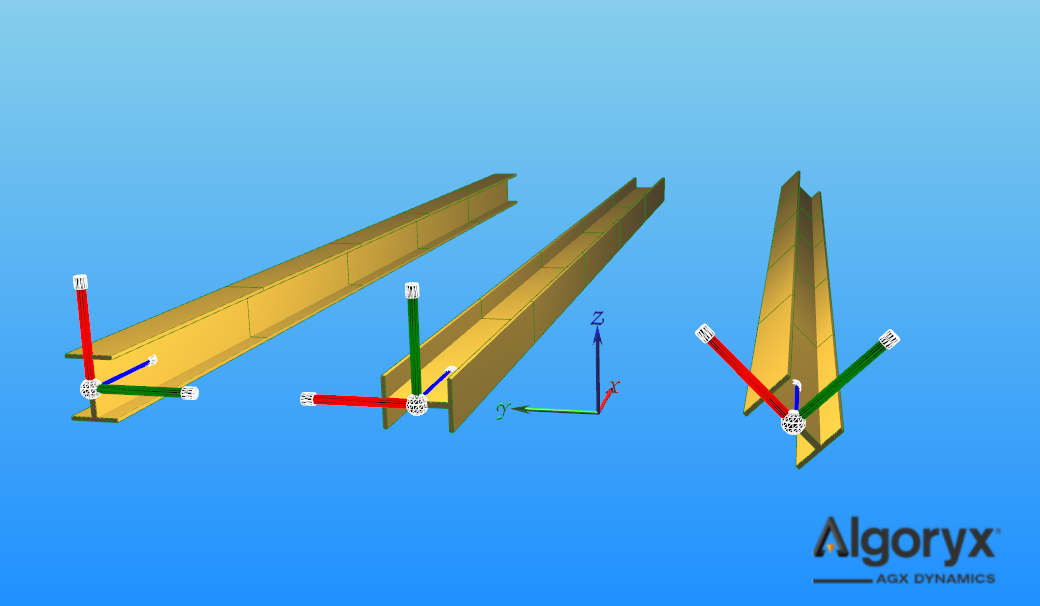
Fig. 27.9 The world frame is the frame without connection to a beam. Initialized beam with rotation along world x with given world up, from left to right: z, y, (y + z) / |y + z|
Note
The beam will be aligned with the given forward direction, while the world up direction is used to find the remaining beam frame directions - up (x) and right (y). The world up direction is normally just the up world axis you use in your simulation.
27.2.2.2. Set Transform
Similar to Set Rotation, beam transforms can be calculated using the static method agxModel::Beam::calculateTransform,
taking an additional argument start position in world coordinate frame.
agxModel::IBeamRef model = new agxModel::IBeam( 0.15, 0.20, 0.01, 0.015 );
const auto beamForwardWorld = agx::Vec3::X_AXIS();

agxModel::BeamRef beam1 = new agxModel::Beam( model, 5u, 5.0 );
beam1->setRotation( agxModel::Beam::calculateTransform( /* startPosition */ agx::Vec3( 0, 1.5, 0 ),
                                                        /* forward */ beamForwardWorld,
                                                        /* worldUp */ agx::Vec3::Z_AXIS() ) );
simulation->add( beam1 );

agxModel::BeamRef beam2 = new agxModel::Beam( model, 5u, 5.0 );
beam2->setRotation( agxModel::Beam::calculateTransform( /* startPosition */ agx::Vec3( 0, 0.5, 0 ),
                                                        /* forward */ beamForwardWorld,
                                                        /* worldUp */ agx::Vec3::Y_AXIS() ) );
simulation->add( beam2 );

agxModel::BeamRef beam3 = new agxModel::Beam( model, 5u, 5.0 );
beam3->setRotation( agxModel::Beam::calculateTransform( /* startPosition */ agx::Vec3( 0, -0.5, 0 ),
                                                        /* forward */ beamForwardWorld,
                                                        /* worldUp */ agx::Vec3::Y_AXIS() +
                                                                      agx::Vec3::Z_AXIS() ) );
simulation->add( beam3 );
The final beam configurations are identical to the scene in Set Rotation where setPosition is used.
27.2.2.3. From To Position
Beams can be instantiated, initialized and transformed using the static method agxModel::Beam::create - taking beam start position and
end position in world coordinate frame, Beam Model, resolution and world up. The resulting beam length will become
\(L = \left|\text{endPosition} - \text{startPosition}\right|\).
agxModel::IBeamRef model = new agxModel::IBeam( 0.15, 0.20, 0.01, 0.015 );
const auto beamForwardWorld = agx::Vec3::X_AXIS();

agxModel::BeamRef beam1 = agxModel::Beam::create( /* startPosition */ agx::Vec3( 0, 1.5, 0 ),
                                                  /* endPosition */ agx::Vec3( 5.0, 1.5, 0 ),
                                                  /* model */ model,
                                                  /* resolution */ 5u,
                                                  /* worldUp */ agx::Vec3::Z_AXIS() );
simulation->add( beam1 );

agxModel::BeamRef beam2 = agxModel::Beam::create( /* startPosition */ agx::Vec3( 0, 0.5, 0 ),
                                                  /* endPosition */ agx::Vec3( 5.0, 0.5, 0 ),
                                                  /* model */ model,
                                                  /* resolution */ 5u,
                                                  /* worldUp */ agx::Vec3::Y_AXIS() );
simulation->add( beam2 );

agxModel::BeamRef beam3 = agxModel::Beam::create( /* startPosition */ agx::Vec3( 0, -0.5, 0 ),
                                                  /* endPosition */ agx::Vec3( 5.0, -0.5, 0 ),
                                                  /* model */ model,
                                                  /* resolution */ 5u,
                                                  /* worldUp */ agx::Vec3::Y_AXIS() +
                                                                agx::Vec3::Z_AXIS() );
simulation->add( beam3 );
The final beam configurations are identical to the scene in Set Rotation.
27.2.3. Attaching Beams
Beams has utility methods for attaching segments to other bodies (or world). The attachment constraint frames are aligned with frame of the beam in context, and the constraint is created, configured and then returned, i.e., not added nor tracked by the beam and is not added to the simulation.
Example of a cantilever beam, attached rigidly to world at begin, and a fixed ended beam, attached rigidly to world at begin and end.
/**
Utility method to attach the first segment of this beam at begin (of the segment) to
another rigid body and optionally adopt the material properties of the model of this beam.
\note The returned lock joint won't be added to the simulation or to this beam and this beam
      has to be initialized.
\param otherRb - other rigid body to attach first segment to - nullptr is world
\param adoptModelProperties - calculate compliance and damping of the attachment given the
                              beam model of this beam
\return lock joint if valid, otherwise nullptr (e.g., \p segment is null or not part of this beam)
*/
agx::LockJointRef attachBegin( agx::RigidBody* otherRb = nullptr,
                               agx::Bool adoptModelProperties = false ) const;

/**
Utility method to attach the last segment of this beam at end (of the segment) to
another rigid body and optionally adopt the material properties of the model of this beam.
\note The returned lock joint won't be added to the simulation or to this beam and this beam
      has to be initialized.
\param otherRb - other rigid body to attach first segment to - nullptr is world
\param adoptModelProperties - calculate compliance and damping of the attachment given the
                              beam model of this beam
\return lock joint if valid, otherwise nullptr (e.g., \p segment is null or not part of this beam)
*/
agx::LockJointRef attachEnd( agx::RigidBody* otherRb = nullptr,
                             agx::Bool adoptModelProperties = false ) const;
agxModel::RectangularBeamRef model = new agxModel::RectangularBeam( 0.10, 0.12 );

// Cantilever beam, attached rigidly at begin, to world.
auto cantileverBeam = agxModel::Beam::create( agx::Vec3( 0, 0, 0 ),
                                              agx::Vec3( 3, 0, 0 ),
                                              model,
                                              150u );
agx::LockJointRef cantileverAttachment = cantileverBeam->attachBegin();
cantileverAttachment->setCompliance( 1.0E-14 );
simulation->add( cantileverAttachment );
simulation->add( cantileverBeam );

// Fixed ended beam, attached rigidly at begin and end, to world.
auto fixedBeam = agxModel::Beam::create( agx::Vec3( 0, 0.5, 0 ),
                                         agx::Vec3( 3, 0.5, 0 ),
                                         model,
                                         150u );
agx::LockJointRef fixedBeginAttachment = fixedBeam->attachBegin();
agx::LockJointRef fixedEndAttachment = fixedBeam->attachEnd();
fixedBeginAttachment->setCompliance( 1.0E-14 );
fixedEndAttachment->setCompliance( 1.0E-14 );
simulation->add( fixedBeginAttachment );
simulation->add( fixedEndAttachment );
simulation->add( fixedBeam );
Another example with guide and support beams. Both beam starts at and is attached to ground/world. The support beam end center is attached to the guide beam surface. This example also examines how the guide vs. support beam attachment frame differs depending on context.
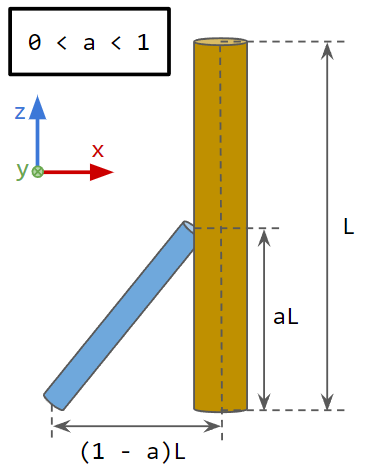
Fig. 27.10 Guide and support beams where the support beam start and end depends on the guide beam length and a scale.
/**
Utility method to attach a given segment (of this beam) at a local segment position to
another rigid body and optionally adopt the material properties of the model of this beam.
\note The returned lock joint won't be added to the simulation or to this beam and this beam
      has to be initialized.
\param segment - segment of this beam to attach
\param localSegmentPosition - beam segment attachment position given in local segment frame
\param otherRb - other rigid body to attach \p segment to - nullptr is world
\param adoptModelProperties - calculate compliance and damping of the attachment given the
                              beam model of this beam
\return lock joint if valid, otherwise nullptr (e.g., \p segment is null or not part of this beam)
*/
agx::LockJointRef attach( BeamSegment* segment,
                          agx::Vec3 localSegmentPosition,
                          agx::RigidBody* otherRb = nullptr,
                          agx::Bool adoptModelProperties = false ) const;
agxSDK::AssemblyRef createGuideSupport( agx::Real radius,
                                        agx::UInt resolution,
                                        agx::Real L,
                                        agx::Real a,
                                        agx::Bool guideIsAttachmentParent )
{
  agxSDK::AssemblyRef assembly = new agxSDK::Assembly();

  const auto supportRadius = 0.85 * radius;
  const auto guideThickness = 5.0E-2 * radius;
  const auto supportThickness = 5.0E-2 * supportRadius;
  const auto supportResolution = agx::UInt( agx::Real( resolution ) * a + 0.5 );

  agxModel::BeamModelPropertiesRef properties = new agxModel::BeamModelProperties( 190.0E9,
                                                                                   0.31 );
  agxModel::HollowCircularBeamRef guideModel = new agxModel::HollowCircularBeam( radius,
                                                                                 guideThickness,
                                                                                 properties );
  agxModel::HollowCircularBeamRef supportModel = new agxModel::HollowCircularBeam( supportRadius,
                                                                                   supportThickness,
                                                                                   properties );

  agxModel::BeamRef guideBeam = agxModel::Beam::create( agx::Vec3( 0, 0, 0 ),
                                                        agx::Vec3( 0, 0, L ),
                                                        guideModel,
                                                        resolution );
  assembly->add( guideBeam );

  const auto supportBeginPosition = guideBeam->getBeginPosition() -
                                    ( 1.0 - a ) * L * agx::Vec3::X_AXIS();
  auto attachmentGuideSegment = guideBeam->getSegment( a * L );
  const auto attachmentGuideFrame = attachmentGuideSegment->getRigidBody()->getFrame();
  // Distance along the local z axis of the guide beam segment that
  // we're attaching the support beam.
  const auto localAttachmentLength = a * L -
                                     // Rest length to the start of the segment.
                                     guideBeam->findRestLengthTo( attachmentGuideSegment );
  const auto supportEndPosition = attachmentGuideFrame->transformPointToWorld( guideModel->getRadius(),
                                                                               0.0,
                                                                               localAttachmentLength );

  agxModel::BeamRef supportBeam = agxModel::Beam::create( supportBeginPosition,
                                                          supportEndPosition,
                                                          supportModel,
                                                          supportResolution );
  assembly->add( supportBeam );

  agxUtil::setEnableCollisions( guideBeam, supportBeam, false );

  agx::LockJointRef guideSupportAttachment = nullptr;
  // If true, we create the attachment given 'guideBeam', so the
  // attachment frames will align with the guide beam frame.
  if ( guideIsAttachmentParent ) {
    guideSupportAttachment = guideBeam->attach( attachmentGuideSegment,
                                                agx::Vec3( guideModel->getRadius(),
                                                           0,
                                                           localAttachmentLength ),
                                                // Support beam last segment rigid body is
                                                // attached to the guide beam.
                                                supportBeam->getSegments().back()->getRigidBody() );
    // Applying constraint properties (compliance and damping) of the
    // guide beam model to the attachment, but twice as stiff when the
    // attachment can be assumed to be more rigid.
    guideBeam->calculateSegmentStiffnessDamping().apply( guideSupportAttachment, 2.0 );
  }
  // If false, we create the attachment given 'supportBeam' and
  // the attachment frames will align with the support beam frame.
  else {
    guideSupportAttachment = supportBeam->attachEnd( attachmentGuideSegment->getRigidBody() );
    // Applying constraint properties (compliance and damping) of the
    // support beam model to the attachment, but twice as stiff when the
    // attachment can be assumed to be more rigid.
    supportBeam->calculateSegmentStiffnessDamping().apply( guideSupportAttachment, 2.0 );
  }
  assembly->add( guideSupportAttachment );

  return assembly;
}
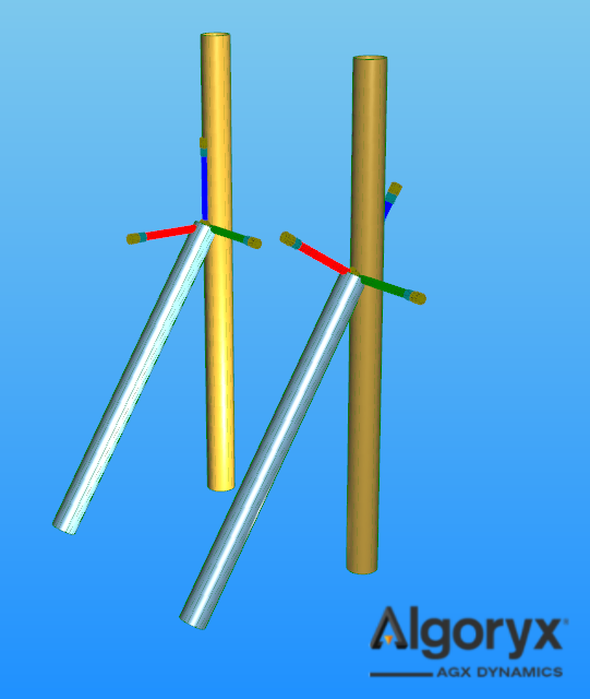
Fig. 27.11 Result calling createGuideSupport twice with guideIsAttachmentParent as true (left)
and false (right).
27.2.3.1. Adopt Model Properties
Constraint compliance and damping time in the constraints between beam segments depends on the resolution and length of the beam, and cross section area and moment of inertia of the model. When the beam is attached to another object or world, it’s possible to transfer the beam model properties to the attachment constraint. E.g.,
// Stiffness and damping time of the constraints in the beam.
agxModel::BeamStiffnessDamping beamStiffnessDamping = beam->calculateSegmentStiffnessDamping();
// Attach begin of the beam to world.
agx::LockJointRef attachment = beam->attachBegin();
// Apply beam properties as if 'attachment' was part of the beam.
beamStiffnessDamping.apply( attachment, /* stiffness scale */ 1.0 );
simulation->add( attachment );
Similarly, all agxModel::Beam::attach* methods has an argument adoptModelProperties, which defaults to false,
that will if true, transfer the beam properties to the constraint as if the attachment is rigidly attached.
Through tests, by performing Newton’s method to minimize the deflection error (Euler-Bernoulli) for cantilever beams, it
has been shown that the beam model properties cannot be applied without modification. The scale of the stiffness depends on the length
and resolution of the beam but a decent approximation is that the stiffness has to be scaled in the range [2.0, 2.5]. If
adoptModelProperties = true the stiffness is scaled by 2.3, identical as,
agx::LockJointRef attachment = beam->attachBegin();
// Approximately rigidly attached to world as the default implementation.
beamStiffnessDamping.apply( attachment, /* stiffness scale */ 2.3 );
simulation->add( attachment );