Tutorial 02 — Introduction to Automatic Assembly
This tutorial will guide you through the basics of modeling mechanical systems using the built-in SNAP feature in the Physics3D bundle of OpenPLX. Using two building blocks—an axle and a link with several holes—we will demonstrate how to use SNAP to assemble mechanical systems.
The links_and_axles.openplx OpenPLX file contains the full tutorial content.
About SNAP
SNAP is designed to manage hierarchical tree structures of physical systems. At its core, a Physics3D.Interactions.Mate has two MateConnectors, which define the interaction. Using SNAP, OpenPLX attempts to find a local_transform for the owner or its parent, aligning the MateConnectors relative to their common ancestor, Physics3D.System.
Key behaviors of SNAP:
-
RigidBodies or Systems with a declared local_transform are excluded from SNAP.
-
SNAP will assemble the system by moving RigidBodies and Systems without a local_transform, placing them to align MateConnectors in space.
-
SNAP may move grandparent Physics3D.Systems without a declared local_transform to fulfill alignment.
-
For ambiguous systems with multiple assembly options, SNAP’s results may vary depending on the order of the Mate definitions.
To debug ambiguities, run agxViewer with --enableOpenPlxDebugLogs trace and look for Forcing
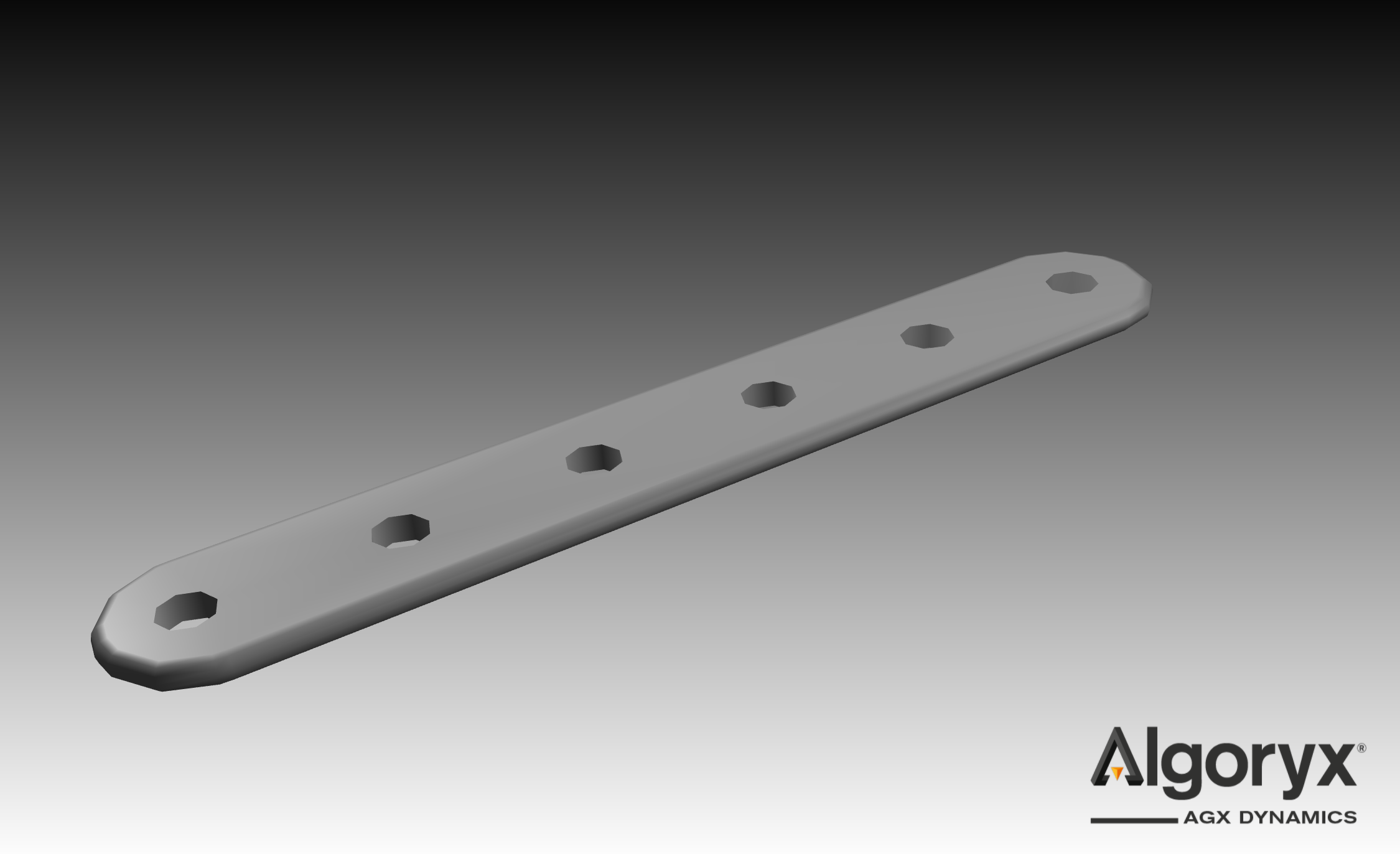
Step 1: Import the Link
Let's model the Link as a RigidBody with an ExternalTriMeshGeometry for both the
visual object and the collision geometry. Create a file called links_and_axles.openplx with the following content.
Link is Physics3D.Bodies.RigidBody:
    scale is Real: 1.0
    geometry is Physics3D.Geometries.ExternalTriMeshGeometry:
        path: @"link_with_holes.obj"
        scale: {scale, scale, scale}
    visual is Visuals.Geometries.ExternalTriMeshGeometry:
        path: geometry.path
        scale: geometry.scale
Before we can load it, ensure that link_with_holes.obj is in the same folder as the openplx file you created, it is available under data/openplx/tutorial/t02-Introduction-to-automatic-assembly in your AGX installation. Test the model with agxViewer:
agxViewer links_and_axles.openplx --modelName Link -p
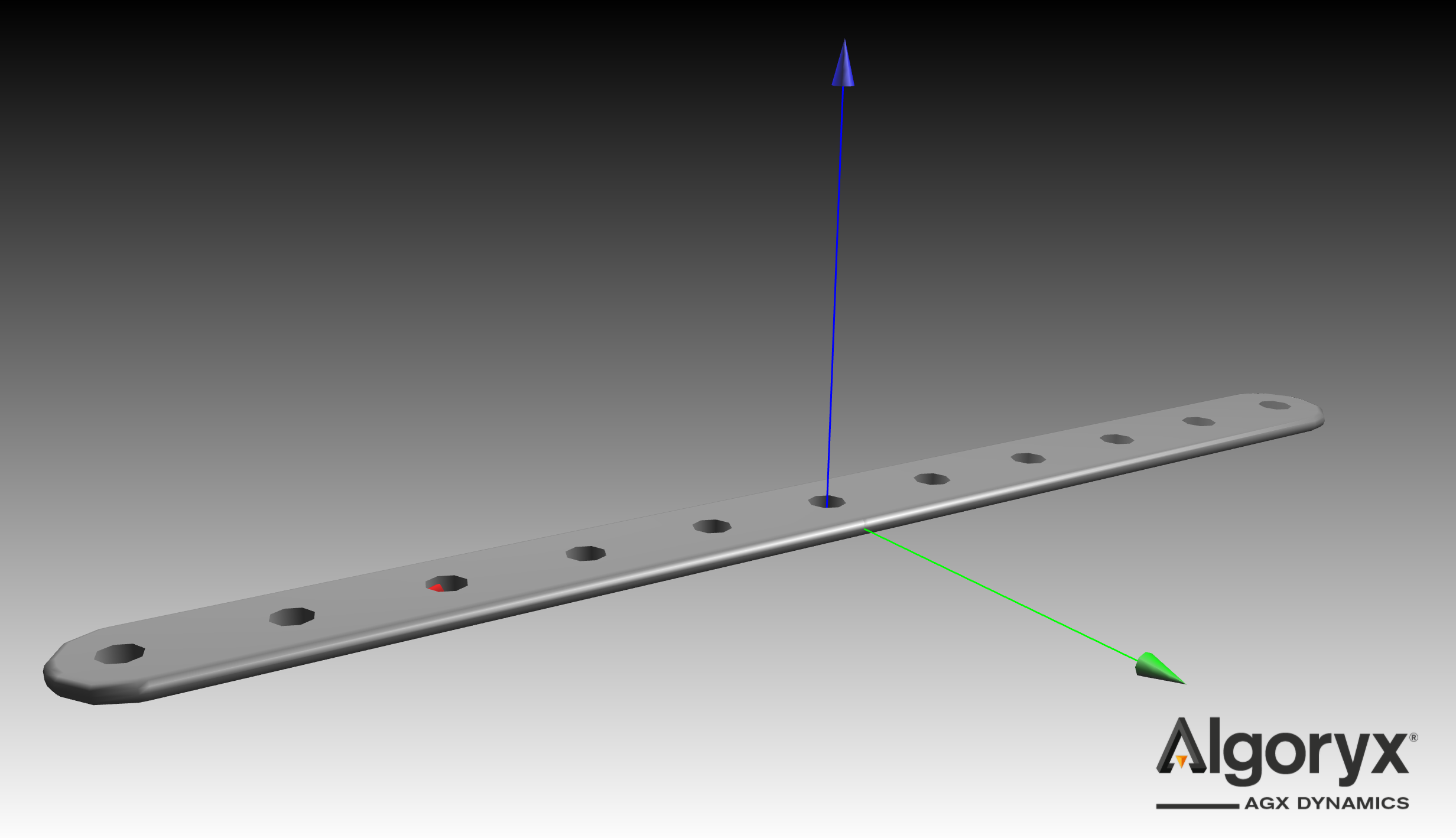
Step 2: Model the Link holes
The link_with_holes.obj defines the geometry. Key details:
-
Holes are separated by 3.2 cm along the X-axis.
-
The mesh origin is offset by 1.4 cm in Y and 1.3 cm in X from the closest hole.
-
Thickness: 0.45 cm.
Next, create HoleConnector model to represent a generic hole. To accommodate scaling, a scale attribute adjusts the connector’s position.
HoleConnector is Physics3D.Interactions.MateConnector:
    scale is Real: 1.0
    local_position is Real
    main_axis: Math.Vec3.Z_AXIS()
    position: Math.Vec3.from_xyz(0.013 * scale + local_position, 0.014 * scale, -0.00225 * scale)
The -0.00225 Z-offset positions the hole at the center plane of the link.
Now, define a LinkWithHoles model and assign six holes, forwarding the scale attribute from the Link to each HoleConnector:
LinkWithHoles is Link:
    hole_separation is Real: 0.032 * scale
    hole_A is HoleConnector:
        scale: scale
        local_position: hole_separation * 0
    hole_B is HoleConnector:
        scale: scale
        local_position: hole_separation * 1
    hole_C is HoleConnector:
        scale: scale
        local_position: hole_separation * 2
    hole_D is HoleConnector:
        scale: scale
        local_position: hole_separation * 3
    hole_E is HoleConnector:
        scale: scale
        local_position: hole_separation * 4
    hole_F is HoleConnector:
        scale: scale
        local_position: hole_separation * 5
Test the model with agxViewer:
agxViewer links_and_axles.openplx --modelName LinkWithHoles -p
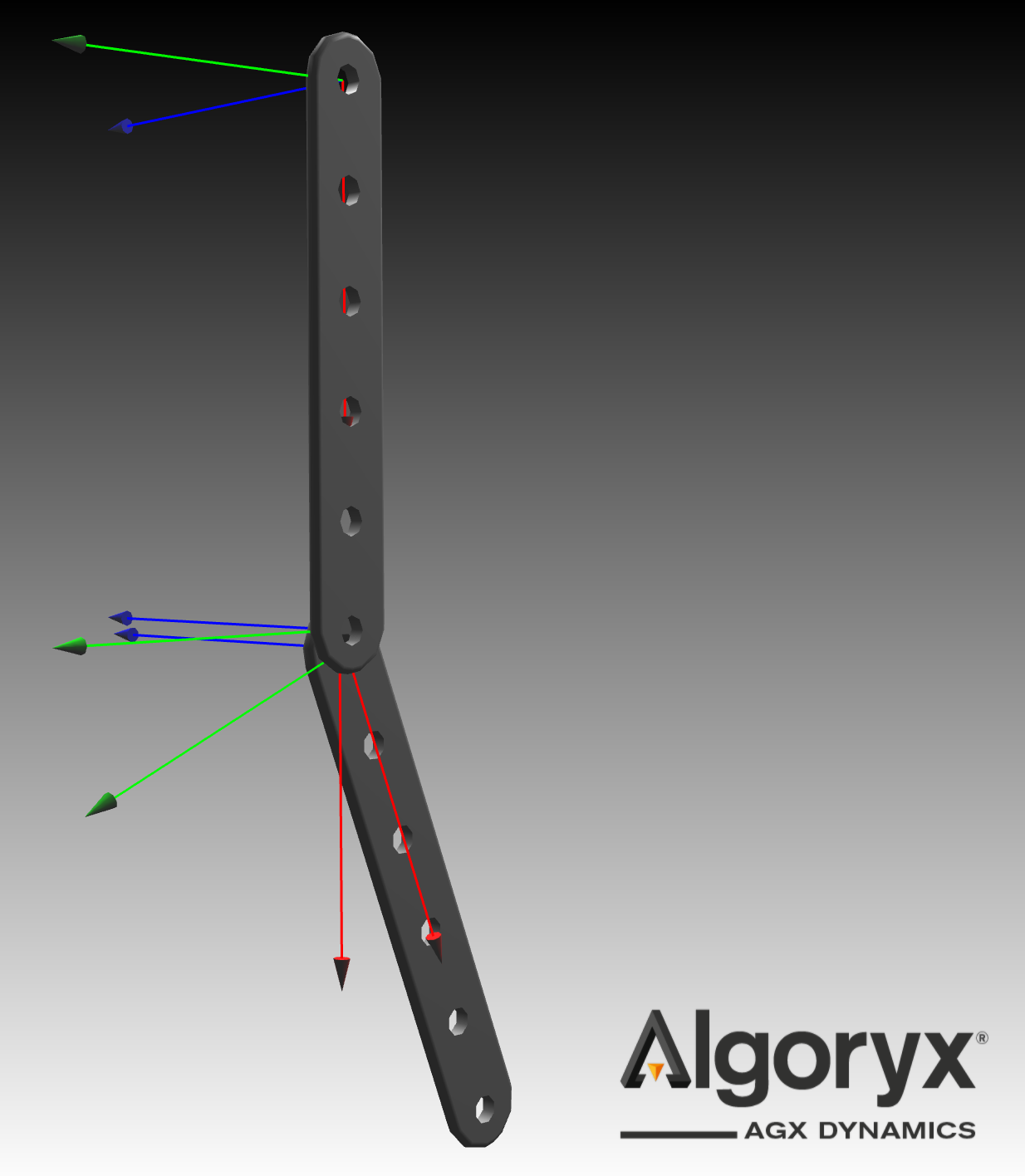
Step 3: Connect two links with a hinge
Connect two instances of LinkWithHoles at specific holes using a Physics3D.Interactions.Hinge.
#--- Previous definitions ---

TwoHingedLinks is Physics3D.System:
    link_1 is LinkWithHoles
    link_2 is LinkWithHoles
    link_hinge is Physics3D.Interactions.Hinge:
        connectors: [link_1.hole_A, link_2.hole_F]
Run this model in agxViewer to see SNAP align hole_A of link_1 with hole_F of link_2.
agxViewer links_and_axles.openplx --modelName TwoHingedLinks -p --openplxDebugRenderFrames
Note that by specifying the --openplxDebugRenderFrames command line argument, you may see an rendered axis for each used MateConnector. To render an axis on the unused MateConnectors, you may add an annotation to them .agx_debug_render_frame: true and they will be visualized no matter if the command line argument is used or not.
The two links are initialized in a overlapping state, which can be seen in the image below.
Because the MateConnector is positioned at the link's center, and SNAP aligns the MateConnector axes, the links initially overlap geometrically. To resolve this, we can reposition the MateConnectors (or holes) to the link's surface instead of at the center plane. Additionally, introducing a small clearance—by offsetting each connector by an extra half millimeter—ensures the link surfaces don't make contact.
The position of each MateConnector influences the local moments on the links, which can introduce asymmetry into the model.
#--- Previous definitions --

TwoNonCollidingHingedLinks is TwoHingedLinks:
    link_1.hole_A.position.z: 0.0005
    link_2.hole_F.position.z: -0.0045 - 0.0005
Next, we want to stop the links from falling to infinity. Do this by creating a new MateConnector that is attached to the world, and a new hinge that connects the world_connector to one of the holes on the links:
TwoNonCollidingHingedLinksWorld is TwoNonCollidingHingedLinks:
    world_connector is Physics3D.Interactions.MateConnector:
        main_axis: Math.Vec3.Y_AXIS()
    world_hinge is Physics3D.Interactions.Hinge:
        connectors: [link_1.hole_F, world_connector]
Load the TwoNonCollidingHingedLinksWorld model with agxViewer to see a double pendulum swing!
agxViewer links_and_axles.openplx --modelName TwoNonCollidingHingedLinksWorld -p --openplxDebugRenderFrames
The double pendulum can be seen below:
Step 4: Non planar linked systems
MateConnectors establish local frames of reference for computing forces and moments. When the links' gravitational forces act in different planes—due to small displacements (as we explored earlier) or scenarios like one link sliding along the hinge axis—the simulation results can vary significantly based on the order of MateConnectors within the connectors array of the Mate.
Later in this tutorial, we'll explore modeling such systems more realistically using axles and examine how SNAP facilitates their automatic assembly.
Below is a model that connects two links using a Cylindrical mate and offsets one link by 10 cm. The rotational stiffness is reduced to visually emphasize the effect.
CylindricalDoublePendulum is Physics3D.System:
    world_connector is Physics3D.Interactions.MateConnector:
        main_axis: Math.Vec3.Y_AXIS()
    world_hinge is Physics3D.Interactions.Hinge:
        connectors: [world_connector, link_1.hole_F]
        initial_angle: Math.PI*0.5
    link_1 is LinkWithHoles:
        hole_A.position.z: 0.0005
    link_2 is LinkWithHoles:
        hole_F.position.z: -0.0045 - 0.0005
    link_cylindrical is Physics3D.Interactions.Cylindrical:
        initial_position: 0.1
        connectors: [link_1.hole_A, link_2.hole_F]
        flexibility becomes Physics3D.Interactions.Flexibility.LinearElasticCylindricalFlexibility:
            around_normal.stiffness: 0.1
            around_cross.stiffness: 0.1
    linear_spring is Physics3D.Interactions.LinearSpring:
        connectors: link_cylindrical.connectors
        position: link_cylindrical.initial_position
Try load this model with agxViewer:
agxViewer links_and_axles.openplx --modelName CylindricalDoublePendulum -p --openplxDebugRenderFrames
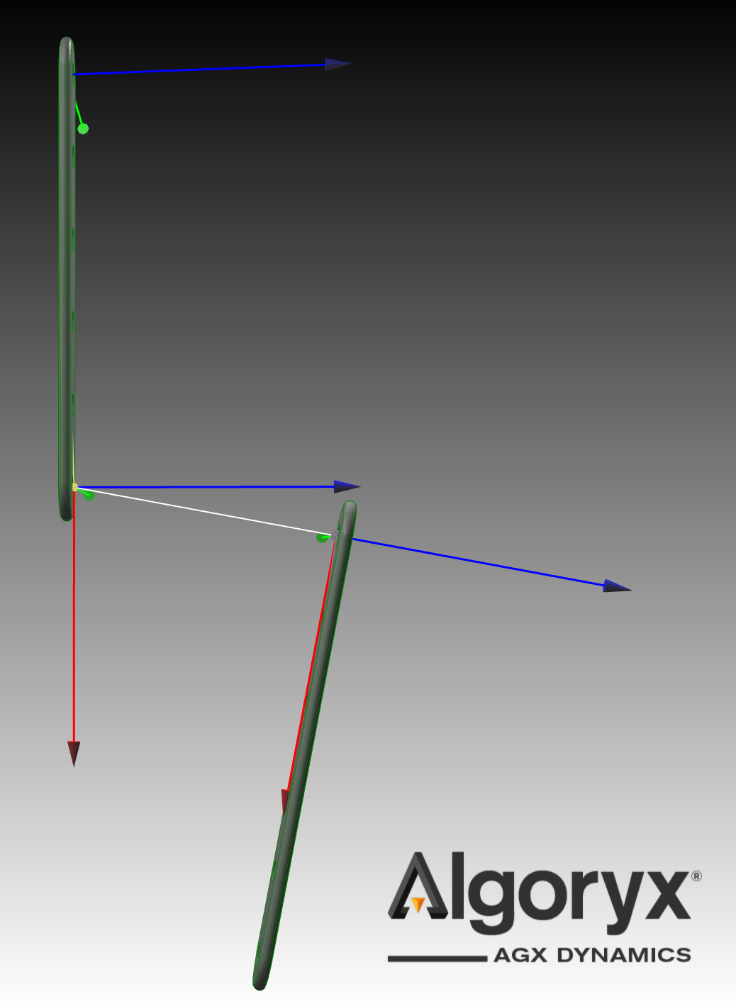
In the cylindrical mate configuration, link_1's mate connector is the first entry in the connectors array. This setup centers the mate relative to link_1, causing link_2 to generate a moment around this central point. The yellow sphere represents the force and moment computation center located at hole_A of link_1, where the gravitational force from link_2 creates a moment.
By pressing g in the 3D view, the AGX debug rendering is activated, where the cylindrical joint axis can be compared with the main_axis of the MateConnector in blue.
If we swap the order of the MateConnector of the Cylindrical, the system looks completely different in a relaxed state.
CylindricalDoublePendulumSwappedOrder is CylindricalDoublePendulum:
    linear_spring.position: -link_cylindrical.initial_position
    link_cylindrical.connectors: [link_2.hole_F, link_1.hole_A]
Try load this model with agxViewer:
agxViewer links_and_axles.openplx --modelName CylindricalDoublePendulumSwappedOrder -p --openplxDebugRenderFrames
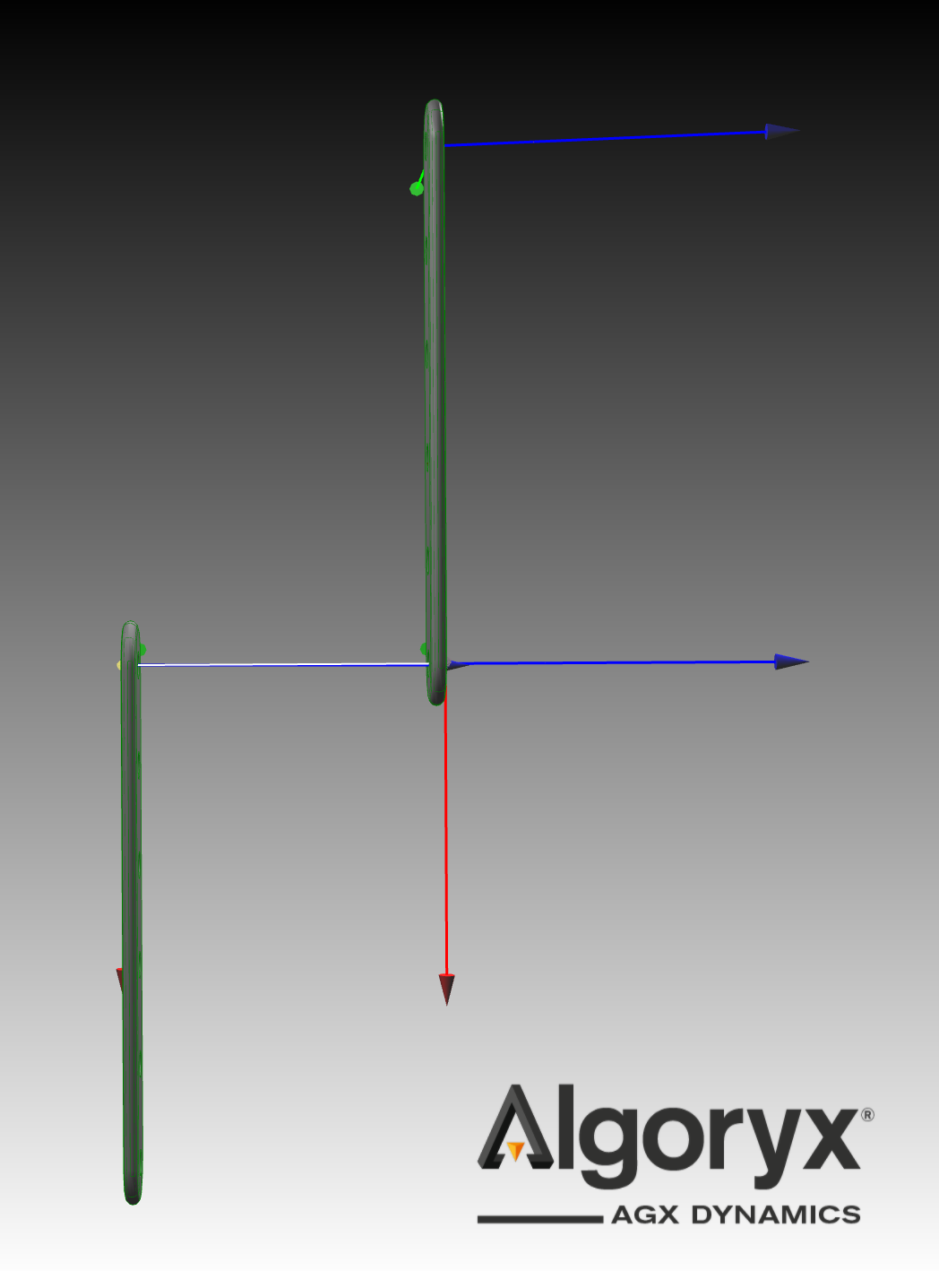
In this cylindrical mate configuration, link_2's mate connector is positioned as the first entry in the connectors array, centering the mate relative to link_2. Notably, there is no moment around the mate center because the sole acting force is link_2's gravitational force.
Here both main_axis of the MateConnectors align with the AGX debug rendering of the Cylindrical axis. Note that in the later image the lower link is now on the opposite side of the upper link, due to the sign of initial_position is relative the first MateConnector in the connectors array.
Step 5: Model and use the axle
For models with asymmetries, as described in Step 3, or when dealing with linked systems involving more than two links along a single axis, Hinges alone may not suffice. To achieve higher fidelity, we introduce an Axle equipped with a MateConnector for connecting the link holes. We begin by defining the AxleNoGeometry, which lacks physical geometry to exclude contact constraints with other components, relying solely on the Mate for link-axle interaction.
AxleNoGeometry is Physics3D.Bodies.RigidBody:
    inertia.mass: 0.01
    inertia.tensor: Physics3D.Bodies.Inertia.symmetric_tensor({0.001,0.01,0.001}, 0, 0, 0)
    visual is Visuals.Geometries.Cylinder:
        radius: 0.0025
        height: 0.3
    connector is Physics3D.Interactions.MateConnector:
        main_axis: {0,1,0}
Let's connect two links to an Axle. When the link mate connectors are listed as the first connector in the Mate's connectors arrays, they establish the frame of reference for force and moment calculations. Set an initial position for each link along the axle, and keep the axle static by setting is_dynamic to false, which disables the dynamics keeping its position fixed and unaffected by gravity and other forces. For demonstration purposes, we'll connect hole_B of link_1 and hole_D of link_2.
TwoLinksOneAxle is Physics3D.System:
    link_1 is LinkWithHoles
    link_2 is LinkWithHoles
    axle is AxleNoGeometry:
        is_dynamic: false
    link_1_mate is Physics3D.Interactions.Cylindrical:
        connectors: [link_1.hole_B, axle.connector]
        initial_position: 0.05
        initial_angle: 0
    link_2_mate is Physics3D.Interactions.Cylindrical:
        connectors: [link_2.hole_D, axle.connector]
        initial_position: -0.05
        initial_angle: 0
By specifying the initial_angle for each mate, SNAP constrains the rotation of the axle relative to the links. However, this constraint is not enforced by the physical simulation.
Load the model with :
agxViewer links_and_axles.openplx --modelName TwoLinksOneAxle -p --openplxDebugRenderFrames
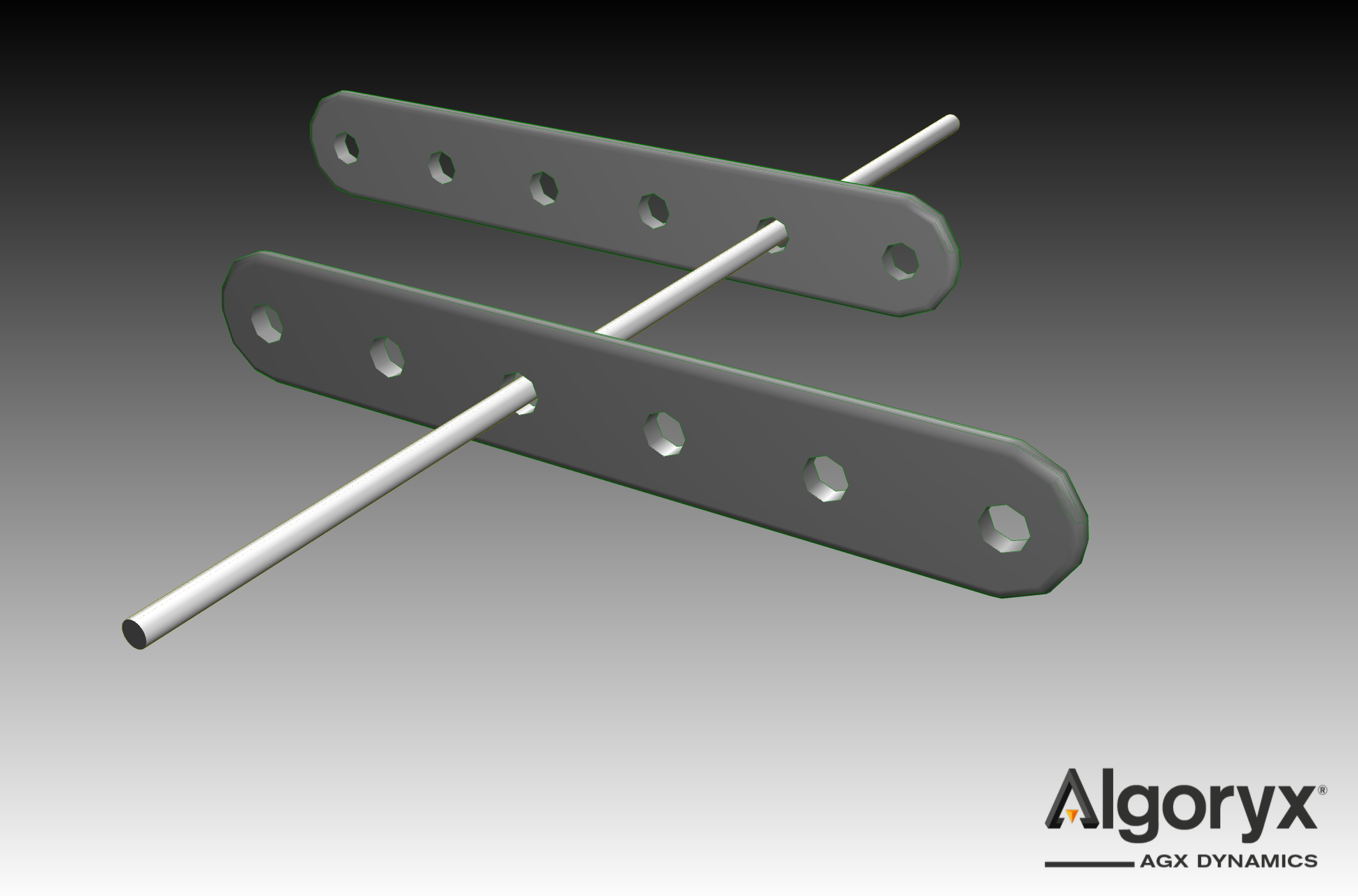
Step 6: Create a looped connection
Let's add another axle to create a closed-loop system
TwoLinksTwoAxles is TwoLinksOneAxle:
    axle_2 is AxleNoGeometry
    link_1_mate_2 is Physics3D.Interactions.Cylindrical:
        connectors: [link_1.hole_D, axle_2.connector]
        initial_position: 0.05
    link_2_mate_2 is Physics3D.Interactions.Cylindrical:
        connectors: [link_2.hole_F, axle_2.connector]
        initial_position: -0.05
Load the model using:
agxViewer links_and_axles.openplx --modelName TwoLinksTwoAxles -p --openplxDebugRenderFrames
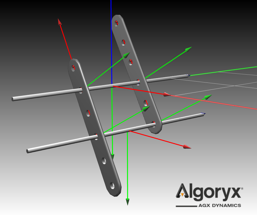
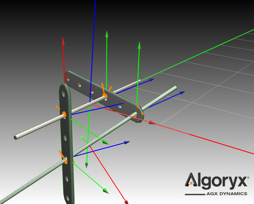
Step 7: Use SNAP for initial states of systems in contact
Even when the Mates are disabled, SNAP will still assemble the system in the same manner. This feature is useful for setting up initial states for systems where geometric contacts are anticipated. Extend AxleNoGeometry by adding a cylinder as its collision geometry.
CollidingAxle is AxleNoGeometry:
    geometry is Physics3D.Geometries.Cylinder:
        radius: visual.radius
        height: visual.height
Extend the TwoLinksTwoAxles model and update the axles to the CollidingAxle type:
TwoLinksTwoAxlesCollision is TwoLinksTwoAxles:
    axle becomes CollidingAxle
    axle_2 becomes CollidingAxle
    link_1_mate.enabled: false
    link_2_mate.enabled: false
    link_1_mate_2.enabled: false
    link_2_mate_2.enabled: false
Lets run this simulation with a finer time discretization, at 200Hz, by adding --timeStep 0.005 to the list of arguments.
agxViewer links_and_axles.openplx --modelName TwoLinksTwoAxlesCollision -p --openplxDebugRenderFrames --timeStep 0.005