22. AGX Vehicle
The AGX Vehicle module provides various functionality for simulating vehicles and machines.
22.1. Tracks
A tracked vehicle is an object containing one or more tracks. Each track consists of two or more wheels and an arbitrary number of track nodes. Each node represents a single track shoe, sometimes referred to as a track link or tread segment
The default AGX Track Model does not model individual track shoes explicitly. Instead, it uses a compact set of bodies and constraints, where the degrees of freedom are determined by the number of wheels rather than the number of track nodes.
Between each pair of wheels, a sensor box body is introduced and constrained to the chassis using a prismatic constraint. Track-ground interaction is represented through the combined behavior of the wheels and sensor boxes, which together define the track topology and tension forces. The track nodes are animated based on wheel geometry and rotational motion, enabling realistic visual rendering.
This approach provides a stable and efficient simulation while capturing the essential dynamics of tracked vehicles.
In addition, a full degrees-of-freedom (Full-DOF) track model is available, where individual track nodes and hinge joints are explicitly represented. This enables higher-realism in the simulations at increased computational cost. The Full-DOF model is a detailed per-node rigid body simulation, offering high realism but requiring more setup effort and computational resources. It is recommended to use the default Track Model in most scenarios.
In AGX Dynamics, the recommended and default Track constructor uses a reference rigid body (typically the vehicle chassis) in vehicle simulations.
agx::RigidBodyRef referenceRigidBody = new agx::RigidBody();
agxVehicle::TrackRef track = new agxVehicle::Track(referenceRigidBody,
                                                  numNodes,
                                                  width,
                                                  thickness);
The sections below describe how to create and configure tracks, add and route wheels, set initial tension and node geometry, and define track stiffness properties such as tensile stiffness.
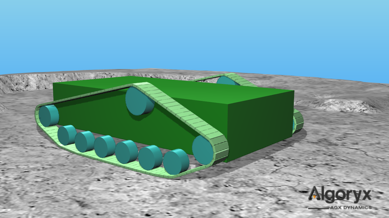
Fig. 22.1 Tracked vehicle with two tracks; each track has nine wheels and 100 nodes.
22.1.1. Track Setup
When modelling a tracked vehicle, the first step is to define the individual parts of the track and then its properties, such as tensile and bending stiffness.
22.1.1.1. agxVehicle::Wheel
A track wheel is a category of wheels used in tracked vehicle systems. These wheels are based on the agxVehicle::Wheel abstraction, which defines the fundamental properties shared by all wheel types. The base class defines an arbitrary geometry using a radius, rigid body, and relative frame.
- Definition:
A wheel has a center, a radius and a rotation axis.
Since the given rigid body can be any user-defined object, the relative frame defines the center and rotation axis of the wheel and is given in the frame of the wheel body.
The resulting frame should have the rotation axis about the y and the up axis along z axis.
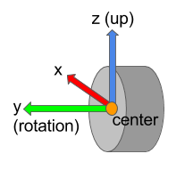
Fig. 22.2 Cylindrical wheel with wheel frame defining center position, rotation and up axes.
To find this relative transform you may use the method Wheel::findRelativeTransform.
// Case 1: Derive the relative transform from an existing hinge constraint.
// The hinge axis will be used as the wheel's rotation axis.
auto relTransform = Wheel::findRelativeTransform( wheelBody, hinge );
// Case 2: Derive the relative transform from an explicit rotation axis.
// The provided axis (in world coordinates)
// will become the wheel's rotation axis.
auto relTransform = Wheel::findRelativeTransform( wheelBody, rotationAxis );
22.1.1.2. agxVehicle::TrackWheel
An agxVehicle::TrackWheel is an agxVehicle::Wheel and inherits the definitions of center,
radius and reference frame. The track wheel adds two important concepts: model and properties.
This means that each track wheel has a certain model and contains a set of properties.
Model |
Description |
|---|---|
Sprocket |
Driving wheel - this wheel’s shaft is connected to the power line or motor. Sprockets are typically geared so that the track nodes do not slip when properly engaged with the sprocket teeth. |
Idler |
Geared, non-powered wheel. Similar surface properties to the sprocket, but this model is not powered. |
Roller |
Intermediate track-return or road wheel. |
The following example shows a cylindrical track wheel with its reference frame aligned with the rigid body. The wheel is attached to the world with a hinge about the rotation axis and zero offset along that axis:
const auto wheelRadius = 0.45;
const auto wheelHeight = 0.35;

agx::RigidBodyRef wheelRb = new agx::RigidBody( "wheelRb" );
wheelRb->add( new agxCollide::Geometry( new agxCollide::Cylinder( wheelRadius, wheelHeight ) ) );

agxVehicle::TrackWheelRef wheel = new agxVehicle::TrackWheel( agxVehicle::TrackWheel::SPROCKET,
                                                              wheelRadius,
                                                              wheelRb );
// Attaching the wheel with a hinge named "hinge" in world (nullptr) and
// 0.0 meters offset along the rotation axis.
auto hinge = wheel->attachHinge( "hinge", nullptr, 0.0 );
hinge->getMotor1D()->setEnable( true );
hinge->getMotor1D()->setSpeed( 1.0 );

simulation->add( wheelRb );
simulation->add( hinge );
It is difficult to provide a concise example with a more complex, non-identity reference frame. To verify the
wheel frame in a specific case, render it using wheel->getTransform(), for example:
#include <agxRender/RenderSingleton.h>
...
  agxRender::debugRenderFrame( wheel->getTransform(), 0.25, agxRender::Color::Red() );
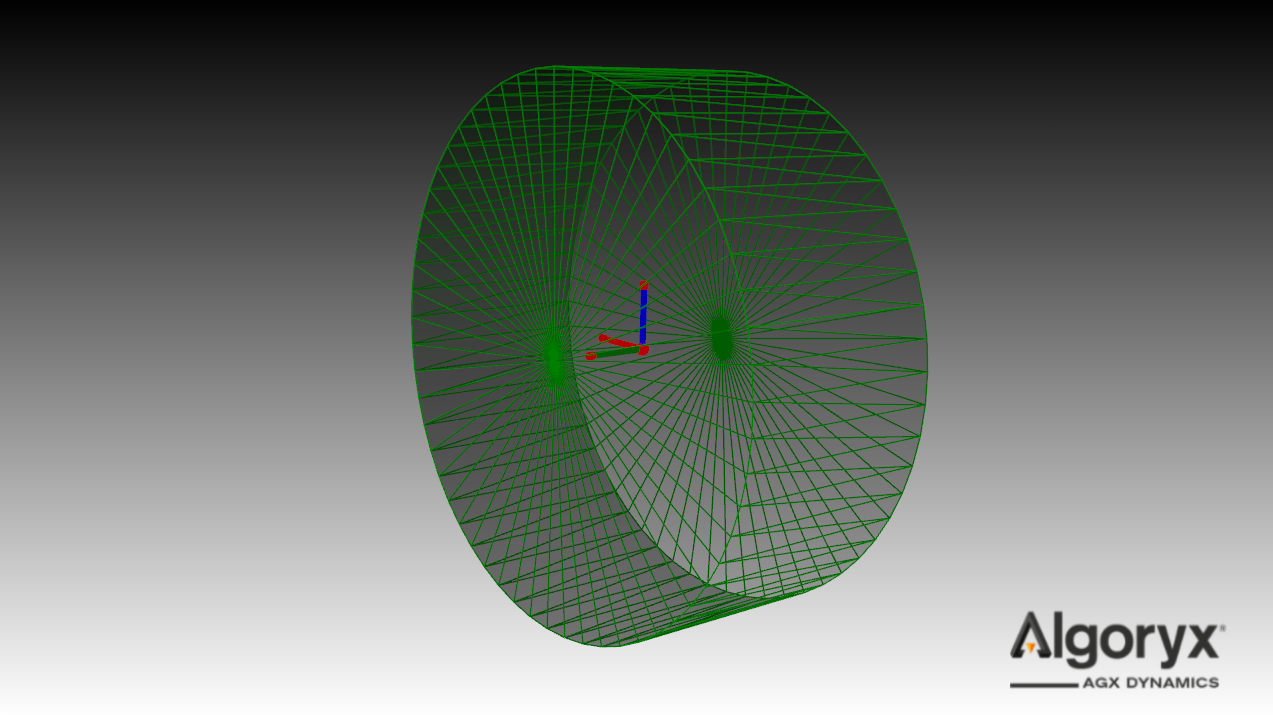
Fig. 22.3 Track wheel with radius 0.45 m and height 0.35 m. Hinged in world with hinge axis along the green (wheel) rotation axis.
Note
When connecting a wheel to another body (for example a chassis or a suspension component) using an agx::Hinge,
make sure the wheel body is specified as the second body in the constraint.
The first body in an agx::Hinge acts as the reference body. For numerical stability, especially at high wheel
angular velocities, the non-rotating body should be used as the reference body.
22.1.1.3. agxVehicle::Track
The class agxVehicle::Track is an assembly object representing a continuous track with a given number of nodes.
22.1.1.4. agxVehicle::Track Initialization
An agxVehicle::Track is instantiated from a referenceRigidBody, the desired number of nodes, width,
thickness of each node, and initialTension. The width and thickness are reference values, i.e., not the
actual geometry dimensions. The thickness value is used to place the nodes as close as possible to the
surface of the wheels.
The initialTension defines the tension in the track after initialization. It specifies the amount by which each node is shortened to generate tension in the track and wheel system. Ideally, the track tension equals the shortening distance multiplied by the track tensile stiffness. Because contacts and other dynamic effects are present, the exact tension after initialization cannot be predicted. A scale factor of four is applied to approximately compensate for frictional effects, and the initial node distance is determined from this scale factor, the specified tension, and the tensile stiffness of the track.
The referenceRigidBody is the reference body that this track is attached to, normally the chassis of a vehicle. Note that the track is routed around track wheels that are connected directly or via links to this rigid body.
The ‘’unknown’’ parameter corresponds to the length of each node. The node length is calculated during initialization to fit the track around the wheels.
22.1.1.4.1. Support geometries
In the track model, a track may be given explicit support geometries using
agxVehicle::Track::addSupportGroupId. This adds the track’s dedicated support
collision group id to a geometry. Geometries carrying that collision group id are treated as
support contacts when the track is contacted from the inside/top side of the track,
for example support rollers or other chassis-mounted guide geometry that is not modeled as
agxVehicle::TrackWheel.
Support geometries are registered with addSupportGroupId and can be removed
with removeSupportGroupId. Contacts between the track and the support geometries are enabled
by default and can be toggled with setEnableCollisionsWithSupport.
22.1.1.4.2. Routing with wheels
Track routing is defined by adding wheels to the track. Given the number of nodes in the track, the node thickness, and the wheel configuration (transform and radius), the routing algorithm calculates the length each node should have for the track to pass outside all wheels.
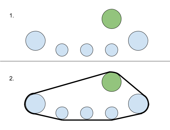
Fig. 22.4 Initial wheel configuration (1) and resulting track route (2).
Note
It does not matter in which order the wheels have been added to the track.
Note
It is currently only possible to initialize tracks in a convex shape.
The following example assumes an array of positioned wheel bodies and an array of wheel radii. The first wheel is set to be the sprocket, and all others are rollers:
// Use your chassis as the rigid body, or nullptr if the track is attached to the world
agx::RigidBodyRef referenceRigidBody = new agx::RigidBody();
agxVehicle::TrackRef track = new agxVehicle::Track( referenceRigidBody,
                                                    numNodes,
                                                    width,
                                                    thickness,
                                                    InitialTrackTension { 2e4 } );
for ( agx::UInt i = 0; i < wheelBodies.size(); ++i ) {
  agxVehicle::TrackWheelRef wheel = new agxVehicle::TrackWheel( i == 0 ?
                                                                  agxVehicle::TrackWheel::SPROCKET :
                                                                  agxVehicle::TrackWheel::ROLLER,
                                                                wheelRadius[ i ],
                                                                wheelBodies[ i ] );
  track->add( wheel );
}

// The track will be initialized when added to a simulation if
// agxVehicle::Track::initialize has not been called explicitly.
simulation->add( track );
22.1.1.4.3. Reference wheel
The reference wheel is used during track initialization. The nodes are positioned in the plane defined by the reference wheel position and rotation axis.
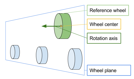
Fig. 22.5 Plane defined by the reference wheel center position and rotation axis.
The reference wheel is defined to be the first sprocket wheel (if any), otherwise first idler wheel (if any), otherwise the first roller.
- Definition:
The reference wheel is the first sprocket wheel added to a track.
22.1.1.4.4. Initial tension
If the track solver finds a solution for the initial configuration and the actual node geometry matches the input thickness, the track tension will be close to zero. If the vehicle or object does not have, for example, a tensioner, the track can instead be initialized with tension.
The initial tension parameter can be specified as either a distance or a force. Using a force value is less precise, as it is difficult to establish an initial state where the resulting tension exactly matches the specified force without simulating the system to equilibrium. When a force is provided, the initial node distance is approximated from the given tension and the tensile stiffness of the track, scaled by a factor of four.
A positive initial node distance shortens the spacing between nodes during initialization, increasing tension. A negative value increases the spacing between nodes, reducing or eliminating tension.
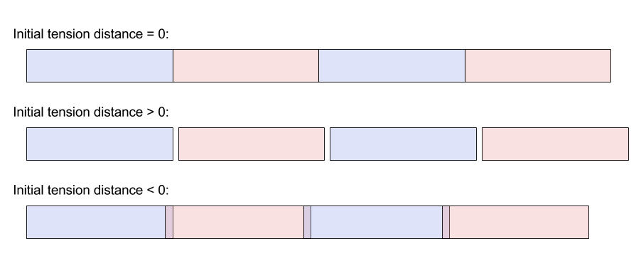
Fig. 22.6 Initial tension distance when zero (no tension), positive (initially stretched) and negative (initially compressed).
22.1.1.4.5. Node geometry
As with the wheels, the geometry of the nodes is completely arbitrary. A box is used by default.
Geometry creation callbacks are invoked after the node has been positioned. The z-axis of the node body points in the
direction of the track, and the model center must be at the start position of the node. The default createGeometryBox
function looks like this:
void createGeometryBox( const TrackNode& node )
{
  // Node half extents = (0.5 * thickness, 0.5 * width, 0.5 * length)
  agxCollide::BoxRef box = new agxCollide::Box( node.getHalfExtents() );
  agxCollide::GeometryRef geometry = new agxCollide::Geometry( box );
  // Model center is at the start of the node, translate geometry forward 0.5 * length (along z).
  const auto transform = agx::AffineMatrix4x4::translate( 0,
                                                          0,
                                                          node.getHalfExtents().z() );
  geometry->setLocalTransform( transform );
  node.getRigidBody()->add( geometry );
}
Adding the track to the simulation without calling initialize beforehand is equivalent to calling
initialize with createGeometryBox and then adding the track to the simulation:
// Default initialization...
simulation->add( track );
// ...is equivalent to:
anotherTrack->initialize( agxVehicle::utils::createGeometryBox );
simulation->add( anotherTrack );
The following example shows two tracks: one initialized with several spheres per node using an initialization function, and the other with capsules using an interface:
class NodeCapsuleInitializer : public agxVehicle::TrackNodeOnInitializeCallback
{
  public:
    NodeCapsuleInitializer() {}

    virtual void onInitialize( const agxVehicle::TrackNode& node ) override
    {
      agxCollide::CapsuleRef capsule = new agxCollide::Capsule( 0.5 * node.getWidth(),
                                                                node.getLength() );
      node.getRigidBody()->add( new agxCollide::Geometry( capsule ),
                                agx::AffineMatrix4x4::rotate( agx::Vec3::Y_AXIS(),
                                                              agx::Vec3::Z_AXIS() ) *
                                agx::AffineMatrix4x4::translate( 0, 0, 0.5 * node.getLength() ) );
    }

  protected:
    virtual ~NodeCapsuleInitializer() {}
};

const agx::Real sphereRadius = 0.1;
// Creates track with five wheels, 60 nodes and width = thickness = 2.0 * sphereRadius.
agxVehicle::TrackRef sphereTrack = createTrack( 2.0 * sphereRadius, 2.0 * sphereRadius );
agxVehicle::TrackRef capsuleTrack = createTrack( 2.0 * sphereRadius, 2.0 * sphereRadius );

sphereTrack->setPosition( 0, -1, 0 );
capsuleTrack->setPosition( 0, 1, 0 );

// Initializing the sphere track with several spheres as geometry.
sphereTrack->initialize( [sphereRadius]( const agxVehicle::TrackNode& node )
{
  const auto offset = 0.5 * sphereRadius;

  const auto numSpheres = std::max( agx::UInt( node.getLength() / offset +
                                               agx::Real( 0.5 ) ),
                                    agx::UInt( 1 ) );
  const auto dl = node.getLength() / agx::Real( numSpheres );
  agxCollide::GeometryRef geometry = new agxCollide::Geometry();
  auto pos = agx::Vec3( 0, 0, 0 );
  auto dir = agx::Vec3::Z_AXIS();
  for ( agx::UInt i = 0; i < numSpheres; ++i ) {
    geometry->add( new agxCollide::Sphere( sphereRadius ),
                   agx::AffineMatrix4x4::translate( pos ) );
    pos += dl * dir;
  }

  node.getRigidBody()->add( geometry );
} );

// Initializing the capsule track with one capsule per node.
capsuleTrack->initialize( new NodeCapsuleInitializer() );

simulation->add( sphereTrack );
simulation->add( capsuleTrack );
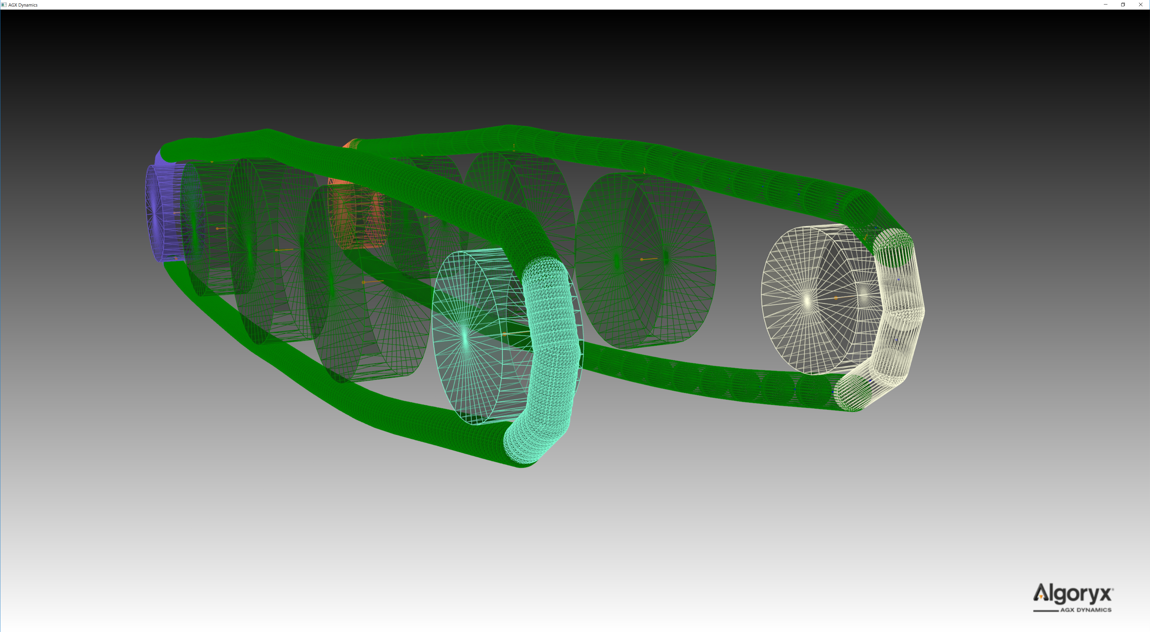
Fig. 22.7 Two tracks initialized with different geometries. Several spheres per node (left) and one capsule per node (right).
Each node does not have to use identical geometry. This example is from tutorial_trackedVehicle.cpp:buildTutorial2,
where every fourth node is thicker than the previous three:
// Two different thickness values along the track. Every fourth node is thicker than the previous three.
const agx::Real defaultThickness = 0.05;
const agx::Real thickerThickness = 0.09;

agxVehicle::TrackRef track = new agxVehicle::Track( 120, 0.4, defaultThickness );
track->add( createTrackWheel( agxVehicle::TrackWheel::Model::SPROCKET, 0.5, 0.3, agx::Vec3( 0, 0, 0 ) ) );
track->add( createTrackWheel( agxVehicle::TrackWheel::Model::ROLLER, 0.6, 0.3, agx::Vec3( 2, 0, 0 ) ) );
track->add( createTrackWheel( agxVehicle::TrackWheel::Model::ROLLER, 0.7, 0.3, agx::Vec3( 4, 0, 0 ) ) );
track->add( createTrackWheel( agxVehicle::TrackWheel::Model::ROLLER, 0.6, 0.3, agx::Vec3( 6, 0, 0 ) ) );
track->add( createTrackWheel( agxVehicle::TrackWheel::Model::IDLER, 0.4, 0.3, agx::Vec3( 8, 0, 0 ) ) );

// Initialization callback called after the track segmentation has been computed.
// When a callback is passed to 'initialize', it is responsible for assigning
// geometries/shapes to the nodes. Note that the track has already calculated
// the node length, which must be taken into account.
agx::UInt counter = 0;
track->initialize( [&]( const agxVehicle::TrackNode& node )
{
  agx::Real heightOffset = 0.0;
  agx::Real thickness = defaultThickness;
  // For every fourth node we add a thicker box.
  if ( ( counter++ % 4 ) == 0 ) {
    thickness = thickerThickness;
    heightOffset = -0.5 * ( thickerThickness - defaultThickness );
  }
  node.getRigidBody()->add( new agxCollide::Geometry( new agxCollide::Box( 0.5 * thickness,
                                                                           0.25,
                                                                           0.5 * node.getLength() ) ),
                            agx::AffineMatrix4x4::translate( heightOffset, 0, node.getHalfExtents().z() ) );
} );
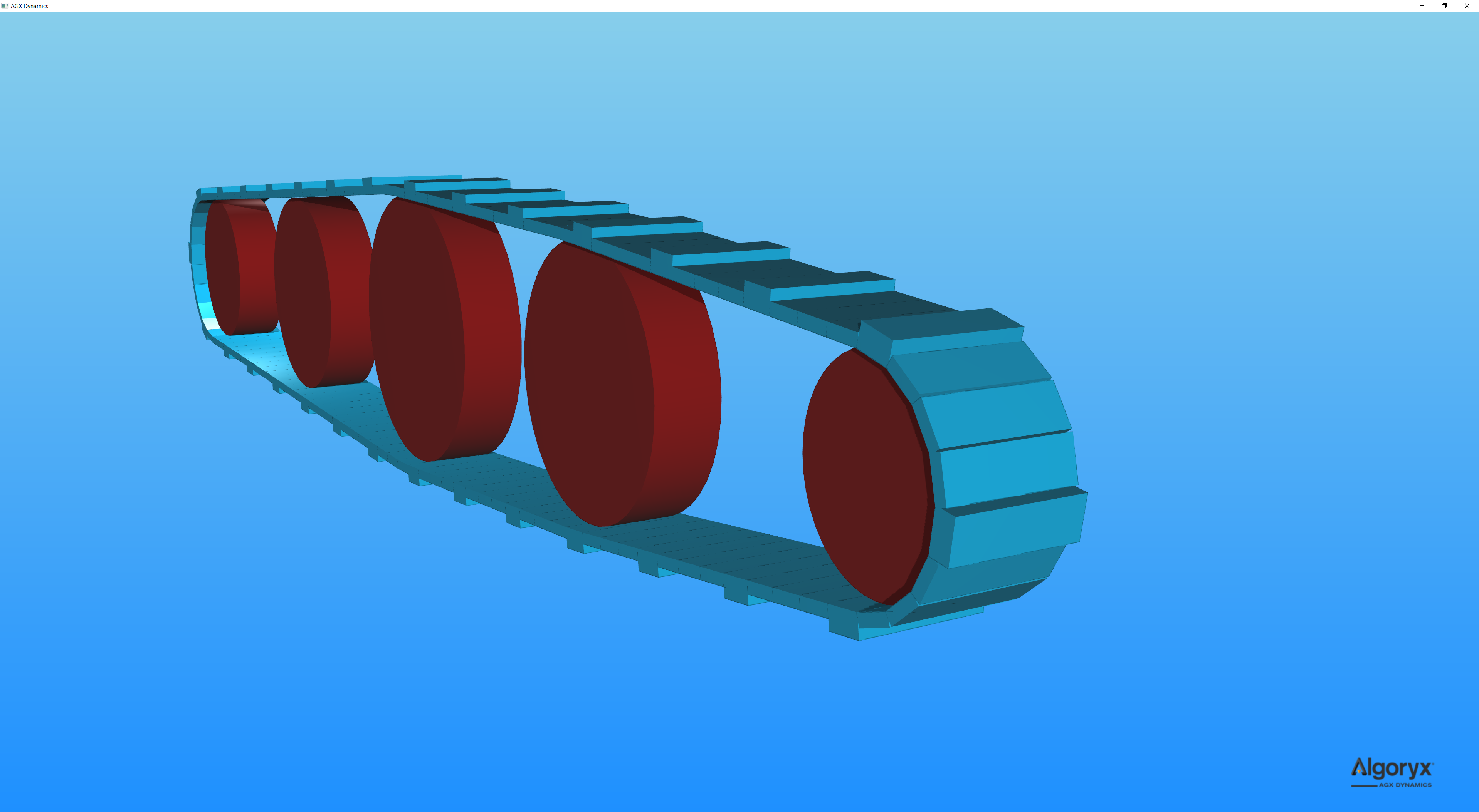
Fig. 22.8 Track initialized with different geometries along the track. Every fourth geometry is larger than the previous three.
22.1.1.4.5.1. Accessing the nodes in a track
Once the track has been initialized, it is possible to iterate over the nodes in a few different ways:
for ( agx::UInt i = 0; i < track->getNumNodes(); ++i ) {
  agxVehicle::TrackNode* node = track->getNode( i );
  ...
}

for ( agxVehicle::TrackNode* node : track->nodes() ) {
  ...
}
Since the track is continuous, i.e., it has no actual start or end, using ranges is often more convenient:
// Iterating all nodes.
for ( agxVehicle::TrackNode* node : track->nodes( { 0u, track->getNumNodes() } ) ) {
  ...
}

// Iterating segments.
const auto numNodesPerSegment = 5u;
for ( agx::UInt nodeIndex = 0; nodeIndex < track->getNumNodes(); nodeIndex += numNodesPerSegment ) {
  agxVehicle::Track::NodeRange range{ track->getIterator( nodeIndex ),
                                      track->getIterator( nodeIndex + numNodesPerSegment ) };
  for ( agxVehicle::TrackNode* node : range ) {
    // Do stuff with the node in range.
  }
}

// Since the track is continuous, it is valid to iterate over six nodes in a track with 100 nodes.
auto range = agxVehicle::Track::NodeRange{ track->getIterator( 1234u ),
                                           track->getIterator( 1234u + 6u ) };
for ( agxVehicle::TrackNode* node : range ) {
  std::cout << node->getIndex() << std::endl;
}

// Prints:
//   34
//   35
//   36
//   37
//   38
//   39
22.1.1.5. Full-DOF Track Model
The Full-DOF Track Model is based on a lumped-element approach with multiple degrees-of-freedom. Each track node is represented by a rigid body connected through hinges, accurately capturing the physical constraints between components and their interactions with terrain and other bodies. This model delivers high physical realism and is well suited for applications where detailed track behavior is important.
However, its complexity can make setup more challenging, especially for fast-moving vehicles. High track speeds require small simulation time steps to maintain accuracy, and can lead to numerical instability in demanding scenarios.
In most cases, this requires additional configuration via Track Properties to tune friction and material parameters, merge nodes for performance, and adjust properties such as damping, hinge limits, and stabilization parameters.
The properties below are associated with track wheels and are assigned by default based on the wheel model type (sprocket, idler, or roller):
Property |
Description |
Model |
|---|---|---|
Merge nodes |
Nodes are merged to the wheel when in contact, mimicking geared interaction (or infinite friction). |
Sprockets and idlers |
Split segments |
Splits merged segments of nodes when in contact with wheels with this property. |
Optional |
Move nodes to rotation plane |
If enabled, when a node is merged to the wheel, the node is moved into the plane defined by the wheel center position and rotation axis. This prevents the track from sliding off its path, but all wheels with MERGE_NODES enabled must be aligned. |
Optional |
Move nodes to wheel |
Similar to move nodes to rotation plane but with this property enabled the node is also placed on the surface of the wheel. |
Optional |
Given these properties, the default behavior per wheel type is as follows:
Sprockets: Instead of frictional contacts, nodes merge with the sprocket, mimicking infinite friction or a geared wheel-track interaction.
Idlers: Default behavior is identical to the sprockets.
Rollers: Frictional contacts. If computational performance is important, make sure the contact material between the rollers and the track nodes has been properly tuned, e.g. high surface viscosity for direct friction models.
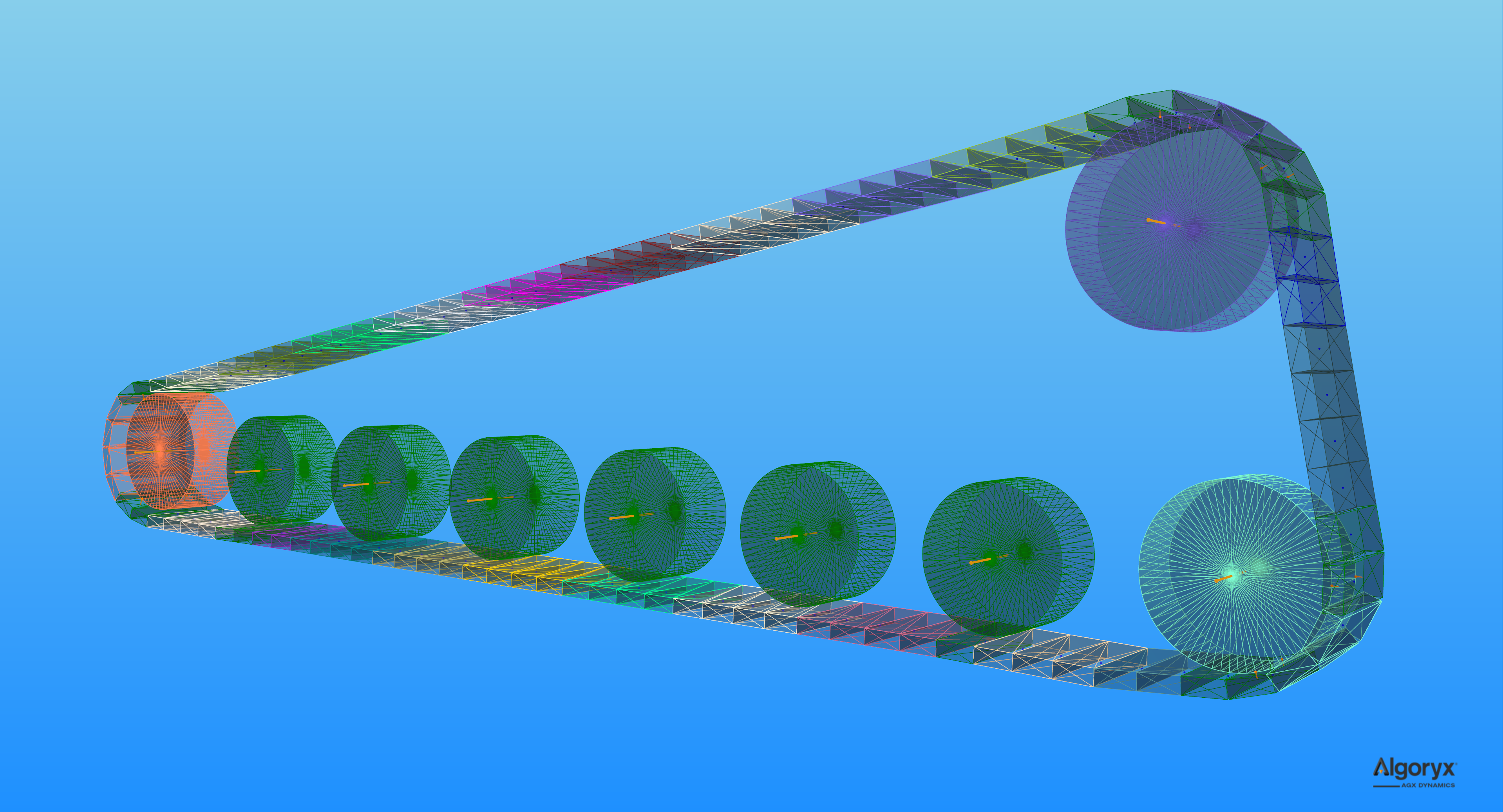
Full-DOF Track Model - Merging segments
For performance reasons, it is possible to enable merging of nodes into segments along the track. The result can be seen in Fig. 22.2, where each segment has a different color. When nodes are merged, several bodies and constraints are not added to the solver, reducing the size of the system matrix. It also becomes possible to perform contact reduction over the whole segment.
To enable merging, which is disabled by default:
auto mergeProperties = track->getInternalMergeProperties();
// Default: false
mergeProperties->setEnableMerge( true );
By default, when merging is enabled, three nodes are merged into a segment. To change the number of nodes per segment:
// Setting the number of nodes per segment to 6 (default 3).
mergeProperties->setNumNodesPerMergeSegment( 6u );
Contact reduction is minimal by default, which means some contacts are removed. The other options are none for no contact reduction, moderate for more aggressive reduction, and aggressive for the most intrusive reduction:
// Default: agxVehicle::TrackInternalMergeProperties::MINIMAL (bin resolution 3)
mergeProperties->setContactReduction( agxVehicle::TrackInternalMergeProperties::MODERATE );
The nodes must be aligned to be merged, to avoid curvature building up along the track. The nodes are constrained together with hinges and, by default, when merging is enabled, the hinge lock is used to force the nodes into their straight resting position. It is possible to toggle this feature and set the compliance and damping of the lock:
// Default: true
mergeProperties->setEnableLockToReachMergeCondition( true );
// Default: 1.0E-11 (very strong)
mergeProperties->setLockToReachMergeConditionCompliance( 1.0E-6 );
// Default: 3.0 / 60.0
mergeProperties->setLockToReachMergeConditionDamping( 6.0 * timeStep );
// Maximum angle > 0 (in radians) when the nodes may merge.
// Default: 1.0E-5
mergeProperties->setMaxAngleMergeCondition( 6.0E-5 );
Full-DOF Track Model - Internal friction in the hinges
Internal friction in the hinges is used to stabilize the nodes in the track under high tension. The default friction coefficient (Stabilizing Hinge Friction Parameter) is relatively high and can work well with default values if the track is relatively large, for example on a large tracked vehicle.
When the friction parameter is too low, the tracks will become unstable.
When the friction parameter is too high, the tracks may appear too stiff to bend, penetrating the wheels and/or preventing the wheels from driving the track.
For example the tracked vehicle in tutorial_trackedVehicle.cpp (Fig. 22.1):
track->getProperties()->setStabilizingHingeFrictionParameter( 1.5 );
To simulate a much smaller, thinner track, where the node mass is significantly lower, the same tutorial file uses:
conveyor->getProperties()->setStabilizingHingeFrictionParameter( 4.0E-3 );
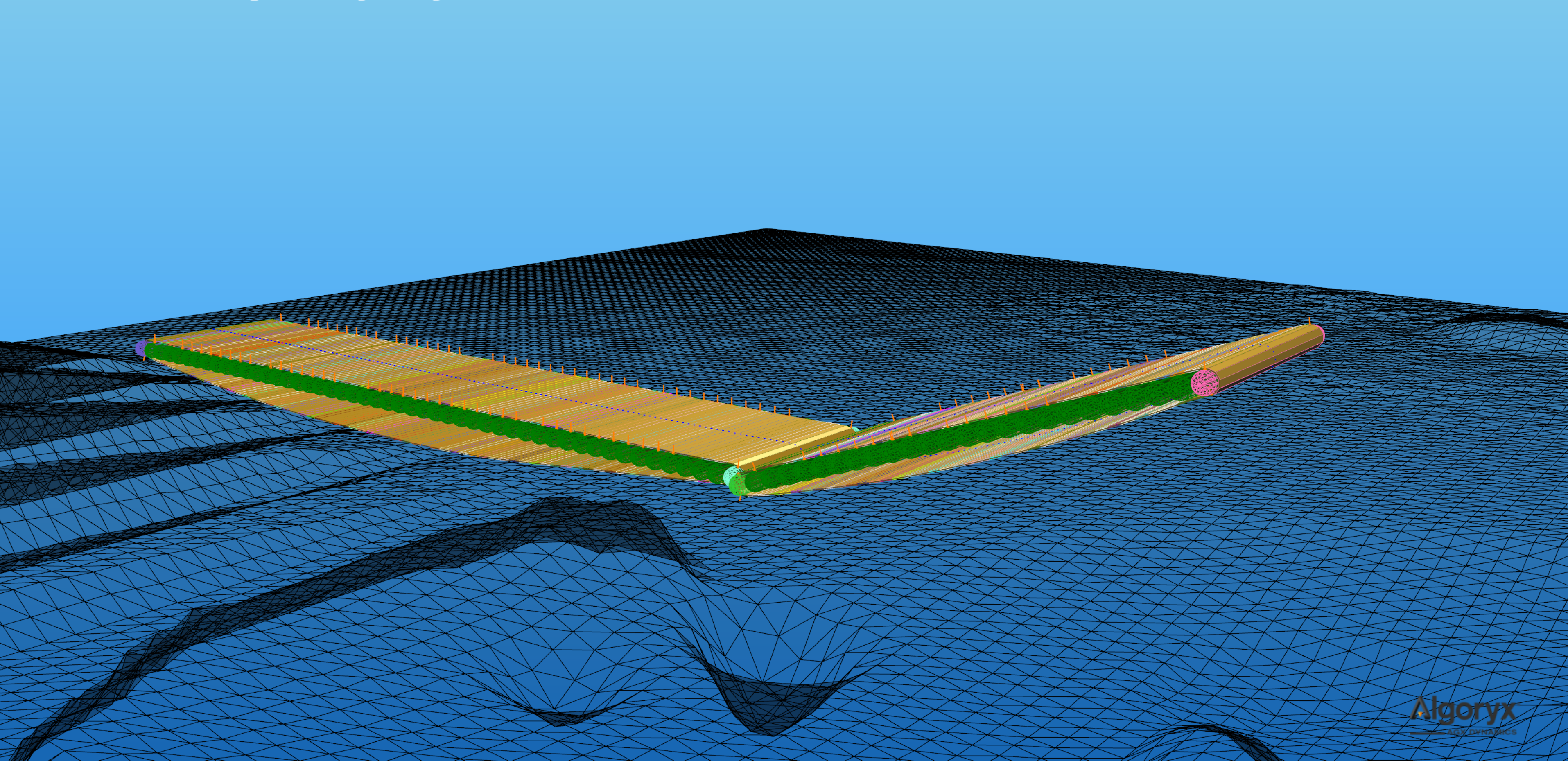
Fig. 22.9 Conveyor belt simulated using agxVehicle::Track, where each roller is represented as a wheel.
22.1.1.6. Switching Between Models
You can switch between the Full-DOF Track Model and the default Track Model at runtime:
// Enable or disable the full degrees-of-freedom model
track->setEnableFullDegreeModel(true);   // Activates the Full-DOF Track Model
track->setEnableFullDegreeModel(false);  // Disable the Full-DOF track model,
                                         // and switch to the Default Track Model.
                                         // This is the default value.

bool isFullDofActive = track->getEnableFullDegreeModel();
22.1.1.7. Using Custom Track Implementations
You can also explicitly assign a custom track implementation. In the example below we use the default Reduced-Order Track Implementation:
// Assign a runtime implementation
agxVehicle::TrackImplementation* customImpl =
         new agxVehicle::ReducedOrderTrackImplementation(referenceRigidBody);
track->setTrackImplementation(customImpl, true);
This allows explicit control over how the track is simulated. The implementation can also be replaced at runtime, allowing you to switch between different models as needed.
22.1.2. Simulation parameters
22.1.2.1. Contact materials and friction models
The default friction model and contact material are normally not suitable for simulating track-ground interactions, mainly because the default friction box is oriented with the world frame and we are interested in separating the contact parameters along the track (traction) and orthogonal to the track (transverse slip/turning behavior).
For tracked systems, use one of the track friction models:
agxVehicle::TrackBoxFrictionModel
agxVehicle::TrackScaleBoxFrictionModel
agxVehicle::TrackIterativeProjectedConeFrictionModel
These models automatically determine the friction directions from the interacting track bodies/geometries, i.e., they do not require an external reference frame (unlike the legacy oriented friction models). This also means a single friction model instance can be shared across an arbitrary number of tracked vehicles/tracks without per-chassis setup.
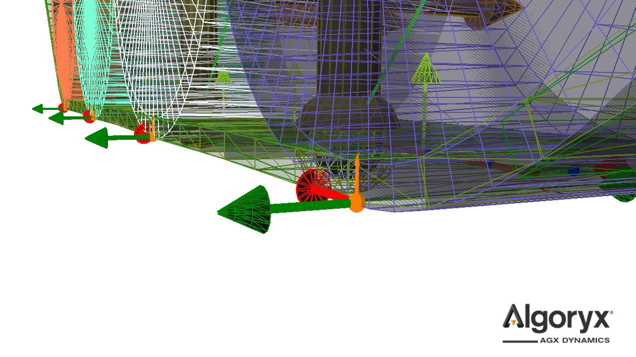
Fig. 22.10 Primary (red) and secondary (green) directions determined by the track friction model. The primary direction is tangent to the track (the track’s positive direction). The track’s positive direction is defined by the rotation axis of the main wheel/sprocket. The sign of the directions is not important for the simulation, what matters is alignment: The primary friction coefficient controls traction along the track, while the secondary friction coefficient controls transverse slip and turning.
Track friction model overview
agxVehicle::TrackBoxFrictionModelBox friction model with track-aligned friction directions. Recommended default for performance/stability when simulating track-ground traction using primary/secondary parameters.
Feature-wise it supports the same key parameters previously used with
agx::ConstantNormalForceOrientedBoxFrictionModel(Section 11.16.3.5):constant normal force magnitude (per-contact friction bound based on a supplied normal force estimate)
optional
scaleWithDepthto scale that bound with contact depth
agxVehicle::TrackScaleBoxFrictionModelScale box friction model with track-aligned friction directions. The nonlinear response of the friction force given the normal force is computationally more expensive but results in accurate friction. See ScaleBoxFrictionModel for further information about this type of friction model.
agxVehicle::TrackIterativeProjectedConeFrictionModelIterative projected cone friction model with track-aligned friction directions. Most accurate, and most computationally expensive, friction model. See IterativeProjectedConeFriction for more details regarding this type of friction model.
General recommendations
Normally, a significant number of nodes are in contact with the ground, floor, or other objects, resulting in many contact points. For best numerical and behavioral performance:
Use a direct friction model solve type (
agx::FrictionModel::DIRECToragx::FrictionModel::DIRECT_AND_ITERATIVE) for the track-ground contact material when possible.Prefer
agxVehicle::TrackBoxFrictionModelfor track-ground interactions, optionally with an estimate of the normal force for each contact point. EnablescaleWithDepthif the system remains within acceptable performance bounds.Set the surface viscosity as high as possible, but low enough to prevent the object from sliding at constant speed.
Use different friction coefficients and surface viscosity along and orthogonal to the tracks. Usually this means higher traction, and potentially lower viscosity, along the tracks, and slightly lower transverse traction with higher viscosity orthogonal to the tracks for smooth turning.
Set restitution to zero for better stability and continuous contacts.
Example from tutorial_trackedVehicle.cpp (vehicle shown in Fig. 22.1):
// Setting up materials.
const agx::Real trackDensity                    = 2000.0;
const agx::Vec2 trackGroundFrictionCoefficients = agx::Vec2( 1000.0, 10 );
const agx::Vec2 trackGroundSurfaceViscosity     = agx::Vec2( 1.0E-7, 8.0E-6 );
const agx::Real trackWheelFrictionCoefficient   = 1.0;
const agx::Real trackWheelSurfaceViscosity      = 1.0E-5;
Note the differences in friction coefficients and viscosity. These must be chosen to match the desired performance, stability, and behavior. Further:
agx::MaterialRef groundMaterial = new agx::Material( "groundMaterial" );
agx::MaterialRef trackMaterial  = new agx::Material( "trackMaterial" );
agx::MaterialRef wheelMaterial  = new agx::Material( "wheelMaterial" );

trackMaterial->getBulkMaterial()->setDensity( trackDensity );

ground->setMaterial( groundMaterial );

trackedVehicle->getRightTrack()->setMaterial( trackMaterial );
for ( const auto wheel : trackedVehicle->getRightTrack()->getWheels() )
  agxUtil::setBodyMaterial( wheel->getRigidBody(), wheelMaterial );

trackedVehicle->getLeftTrack()->setMaterial( trackMaterial );
for ( const auto wheel : trackedVehicle->getLeftTrack()->getWheels() )
  agxUtil::setBodyMaterial( wheel->getRigidBody(), wheelMaterial );
Note that we are separating ground, wheel, and track materials. Normally, it is enough to use the default friction model for contacts between the track nodes and the wheels, but if the wheels do not respond strongly enough to friction, a simplified direct track friction model can be used:
#include <agxVehicle/TrackFrictionModels.h>

// Contact material between track nodes and the wheels.
auto trackWheelContactMaterial =
  simulation->getMaterialManager()->getOrCreateContactMaterial( trackMaterial, wheelMaterial );

// Slightly simplified friction model between the wheels and the track
// where we estimate the normal force constant @ ten times the mass of
// the chassis. Solved direct.
auto trackFmConstantNormalForce = 10.0 * trackedVehicle->getChassis()->getMassProperties()->getMass();

auto trackWheelFrictionModel =
  new agxVehicle::TrackBoxFrictionModel( agx::FrictionModel::DIRECT,
                                         trackFmConstantNormalForce );
trackWheelContactMaterial->setFrictionModel( trackWheelFrictionModel );

// Let the friction coefficient be high and "ease up" the friction constraints
// by using high surface viscosity. Friction properties do not affect the
// sprockets or idlers since the nodes will merge to them, simulating infinite
// stick friction against those geared wheel types.
trackWheelContactMaterial->setFrictionCoefficient( trackWheelFrictionCoefficient );
trackWheelContactMaterial->setSurfaceViscosity( trackWheelSurfaceViscosity );
trackWheelContactMaterial->setRestitution( 0.0 );
The contact material between the track nodes and ground is similar but here we include primary and secondary parameters:
// Contact material between track nodes and the ground.
auto trackGroundContactMaterial =
  simulation->getMaterialManager()->getOrCreateContactMaterial( trackMaterial, groundMaterial );

// Track-ground friction: use primary (along track) and secondary (transverse) parameters.
// This friction model can optionally scale the maximum friction force with contact depth.
auto trackGroundFrictionModel =
  new agxVehicle::TrackBoxFrictionModel( agx::FrictionModel::DIRECT,
                                         trackFmConstantNormalForce,
                                         true /* scaleWithDepth */ );
trackGroundContactMaterial->setFrictionModel( trackGroundFrictionModel );

trackGroundContactMaterial->setFrictionCoefficient( trackGroundFrictionCoefficients.x(),
                                                    agx::ContactMaterial::PRIMARY_DIRECTION );
trackGroundContactMaterial->setFrictionCoefficient( trackGroundFrictionCoefficients.y(),
                                                    agx::ContactMaterial::SECONDARY_DIRECTION );

trackGroundContactMaterial->setSurfaceViscosity( trackGroundSurfaceViscosity.x(),
                                                 agx::ContactMaterial::PRIMARY_DIRECTION );
trackGroundContactMaterial->setSurfaceViscosity( trackGroundSurfaceViscosity.y(),
                                                 agx::ContactMaterial::SECONDARY_DIRECTION );

trackGroundContactMaterial->setRestitution( 0.0 );
22.1.2.2. Track properties agxVehicle::TrackProperties
The parameters and features implemented in the track model are exposed through the agxVehicle::TrackProperties
object. Every track instance has one, and several track instances can share the same object, e.g.:
auto globalProperties = track1->getProperties();
track2->setProperties( globalProperties );
track3->setProperties( globalProperties );

agxVehicle::TrackPropertiesRef otherProperties = new agxVehicle::TrackProperties();
track4->setProperties( otherProperties );
track5->setProperties( otherProperties );
It is also possible to load predefined property sets from the Material Library:
if ( properties->loadLibraryProperties( "steel" ) )
  std::cout << "Loaded track properties from library!" << std::endl;
You can query available library property sets using:
agx::StringVector available = agxVehicle::TrackProperties::getAvailableLibraryProperties();
There are many parameters in the track properties, some more important than others.
This table, under “Property”, lists the accessor and mutator names – just add get or set and remove any spaces,
e.g. Bending Stiffness is accessed as
properties->setBendingStiffness( stiffness, axis ) and
auto k = properties->getBendingStiffness( axis ):
Property |
Description |
Default value |
|---|---|---|
Bending Stiffness |
Resistance to bending deformation per unit length. Typical value is \(E I_a\) where \(E\)
is Young’s modulus and \(I_a\) is the second moment of area. Requires specifying the axis
( |
50 around lateral axis and 1.0e10 around vertical axis |
Tensile Stiffness |
Resistance to stretching/compression in the longitudinal direction per unit length. Higher values give a stiffer track. Default is 1e10 N/m. |
1.0E10 |
Bending Attenuation |
Attenuation factor applied in bending stiffness calculations, per axis. |
2.0 |
Tensile Attenuation |
Attenuation factor applied in tensile stiffness calculations. |
2.0 |
The default track model exposes a set of additional stabilization and tuning parameters, which are generally left unchanged in most simulation scenarios. The parameters below are accessed via:
// This example lowers the vertical stabilization factor to 0.5.
auto trackImplementation = track->getTrackImplementation();
auto model = trackImplementation->asSafe<agxVehicle::ReducedOrderTrackImplementation>();
agxVehicle::ReducedOrderTrackProperties& properties = model->getProperties();
model->setVerticalStabilityScaleFactor( 0.5 );
Property |
Description |
Default value |
|---|---|---|
Bending Stiffness Scale Factor |
The default track model has a vertical stabilization model that filters high-frequency oscillations. This parameter controls the scale of the force applied by the vertical stabilization. Increase this scale factor if you experience unnatural track oscillations under high tension. If the vertical stabilization effect becomes too dominant, noticeable as plastic-like behavior in the track when moved from equilibrium, decrease this scale factor. Note that the strength of the vertical stability depends on track tension, bending stiffness, and this scale factor. |
1.0 |
Sensor Length Scale |
The sensor segments between the track wheels have the same length as the wheel center to center distance multiplied by this scale factor. Decrease this scale factor to shorten the length of the sensors if you experience situations when the track segment sensor is touching the ground when the track tension is low and the track is slack. |
1.0 |
Attach Contacts To Sprocket |
Enable/disable attachment of contact points (between sensor and obstacle) to the sprocket. A contact point transfers torque and force directly to a wheel. The default is true and the contact is associated with the sprocket. If this is false, then the contact points are associated with the nearest wheel. |
true |
22.1.2.3. Full-DOF Track Model - Track properties
For the Full-DOF Track Model, these extra parameters may need some attention when configuring your tracks. These
properties are exposed in the agxVehicle::TrackProperties object.
Property |
Description |
Default value |
|---|---|---|
Torsional Stiffness |
Resistance to twisting around the track’s longitudinal axis. Typical value \((GJ)/L\). This parameter is only used in the Full-DOF Track Model. |
1.0e10 |
Shear Stiffness |
Resistance to shearing deformation per unit length, defined as \(GA/L\). Requires specifying
the axis ( |
1.0e10 along both axes |
Shear Attenuation |
Attenuation factor applied in shear stiffness calculations, per axis. This parameter is only used in the Full-DOF Track Model. |
2.0 |
Torsional Attenuation |
Attenuation factor applied in torsional stiffness calculations. This parameter is only used in the Full-DOF Track Model. |
2.0 |
Min Stabilizing Hinge Normal Force |
Minimum value of the normal force (the hinge force along the track) used in “internal” friction calculations. I.e., when the track is compressed, this value is used with the friction coefficient as a minimum stabilizing compliance. If this value is negative there will be stabilization when the track is compressed. This parameter is only used in the Full-DOF Track Model. |
100 |
Stabilizing Hinge Friction Parameter |
Friction parameter of the internal friction in the node hinges. This parameter scales the normal force in the hinge. This parameter is only used in the Full-DOF Track Model. |
1 |
Enable Hinge Range |
Enable or disable hinge range between track nodes to define how the track may bend. This parameter is only used in the Full-DOF Track Model. |
true |
Hinge Range Range |
The range, in radians, that defines the allowed relative angle between track nodes. This parameter is only used in the Full-DOF Track Model. |
\(-270 \leq \alpha \leq 20\) degrees. |
Enable On Initialize Merge Nodes To Wheels |
When the track has been initialized, some nodes are in contact with the wheels. If this flag is true, the interacting nodes are merged directly to the wheel after initialization. If false, the nodes are merged during the first, or a later, time step. This parameter is only used in the Full-DOF Track Model. |
false |
Enable On Initialize Transform Nodes To Wheels |
True to position/transform the track nodes to the surface of the wheels after the track has been initialized. When false, the routing algorithm positions are used. This parameter is only used in the Full-DOF Track Model. |
true |
Transform Nodes To Wheels Overlap |
When nodes are transformed to the wheels, this is the final target overlap. This parameter is only used in the Full-DOF Track Model. |
1.0E-3 |
Nodes To Wheels Merge Threshold |
Threshold when to merge a node to a wheel. Given a reference direction in the track, this value is the projection of the deviation (from the reference direction) of the node direction onto the wheel radial direction vector. I.e., when the projection is negative the node can be considered “wrapped” on the wheel. This parameter is only used in the Full-DOF Track Model. |
-0.1 |
Nodes To Wheels Split Threshold |
Threshold when to split a node from a wheel. Given a reference direction in the track, this value is the projection of the deviation (from the reference direction) of the node direction onto the wheel radial direction vector. I.e., when the projection is negative the node can be considered “wrapped” on the wheel. This parameter is only used in the Full-DOF Track Model. |
-0.05 |
Num Nodes Included In Average Direction |
Average direction of non-merged nodes entering or exiting a wheel is used as reference direction when splitting off a merged node. This is the number of nodes to include in this average direction. This parameter is only used in the Full-DOF Track Model. |
3 |
Note
The stabilization-related parameters (e.g., Min Stabilizing Hinge Normal Force, Stabilizing Hinge Friction Parameter) and node/wheel merge and hinge range settings are only relevant when using the Full-DOF Track Model. These parameters do not apply to the default Track Model.
The attenuation constants determine how much to attenuate an oscillation above the Nyquist frequency. The default is 2. This may be calculated from a (viscous) damping coefficient; see agxUtil::convertDampingCoefficientToSpookDamping and set attenuation to spook damping time / simulation time step.
22.2. WheelJoint
A WheelJoint is a constraint to attach a wheel to a chassis or the world. The WheelJoint can be created in a few different ways. What they all have in common is that the wheel is the first body and the optional chassis is the second.
When using agx::Frames to construct a WheelJoint, some axes are more important than others. The Y-axis in the first body’s frame specifies the wheel axle. The Z-axis in the second body’s frame is used as suspension axis. When the steering is engaged, the rotation will be around this axis so it can also be referred to as steering axis.
The setup can also be done by using a WheelJointFrame which specifies in world coordinates, the wheel axis, the suspension/steering axis and the intersection point between those two. The two axes that are defined must be perpendicular.
agx::RigidBody* wheel = ... ;

// Position wheel at (1,0,0)
wheel->setPosition( agx::Vec3( 1.0, 0, 0 ) );

// We have the attachment between wheel axle and steering axle at (0.5, 0, 0)
agx::Vec3 worldAttach       = agx::Vec3( 0.5, 0, 0 );

// Wheel attachment point and wheel position are on the wheel axle
agx::Vec3 worldWheelAxle    = agx::Vec3::Y_AXIS();
agx::Vec3 worldSteeringAxle = agx::Vec3::Z_AXIS();

// Specify a frame
auto wheelJointFrame = WheelJointFrame( worldAttach, worldWheelAxle, worldSteeringAxle );

// Create the constraint. In this case, the wheel is attached to the world
agxVehicle::WheelJoint* wheeljoint = new agxVehicle::WheelJoint( wheelJointFrame, wheel, nullptr );

simulation->add( wheeljoint );

// The suspension is locked by default, release...
auto su_lock = wheeljoint->getLock1D( agxVehicle::WheelJoint::SUSPENSION );
su_lock->setEnable( false );

// .. and enable the range instead to show free movement.
auto su_range = wheeljoint->getRange1D( agxVehicle::WheelJoint::SUSPENSION );
su_range->setEnable( true );
su_range->setRange( -0.1, 0.1 );

// If we don't want rotation around the steering axis, we can lock it
// at its current angle
auto st_lock = wheeljoint->getLock1D( agxVehicle::WheelJoint::STEERING );
st_lock->setPosition( wheeljoint->getAngle( agxVehicle::WheelJoint::STEERING) );
st_lock->setEnable( true );
22.2.1. Connecting to a power-line
A WheelJoint can be powered by a power-line by attaching it to an Actuator. A RotationalActuator cannot be used by itself since a WheelJoint has multiple degrees-of-freedom, which means that we need to tell the Actuator which of them it should operate on. This is done by passing a WheelJointConstraintGeometry to the RotationalActuator. The WheelJointConstraintGeometry identifies one of the WheelJoint’s free degree of freedom and we chose which one using the same technique as when getting a Lock1D or a Range1D from it.
Continuing the example above.
agxPowerLine::ConstraintGeometryRef wheelAttachAxis =
  new agxVehicle::WheelJointConstraintGeometry(wheelJoint, agxVehicle::WheelJoint::WHEEL);
agxPowerLine::RotationalActuatorRef actuator =
  new agxPowerLine::RotationalActuator(wheelJoint, wheelAttachAxis);
To control the suspension with a TranslationalActuator we would use agxVehicle::WheelJoint::SUSPENSION instead.
agxPowerLine::ConstraintGeometryRef suspensionAttachAxis =
  new agxVehicle::WheelJointConstraintGeometry(wheelJoint, agxVehicle::WheelJoint::SUSPENSION);
agxPowerLine::TranslationalActuatorRef actuator =
  new agxPowerLine::TranslationalActuator(wheelJoint, suspensionAttachAxis);
For more information on power-line components and how to connect them see AGX PowerLine.
For a complete example see the tutorial_wheel_joint.agxPy Python tutorial.
22.3. Steering
When a car actually turns as shown in Fig. 22.11 a), the steering mechanism is designed to align the wheels simultaneously. The inner wheel will follow a circle with radius \(R\), while the outer wheel follows a concentric circle with radius \(R + W_t\). Note that \(W_t\) refers to the wheel track, \(W_b\) denotes the wheel base.
To minimize the slip and ensure the better turning performance, the front steerable wheels should hold the different steering angles of \(\delta_{\text{in}}\) and \(\delta_{\text{out}}\). According to Ackermann principle, it yields
where \(\delta_{\text{in}}\) refers to the steering angle of the inner wheel, \(\delta_{\text{out}}\) is the ideal steering angle of the outer wheel corresponding to the prescribed \(\delta_{\text{in}}\).
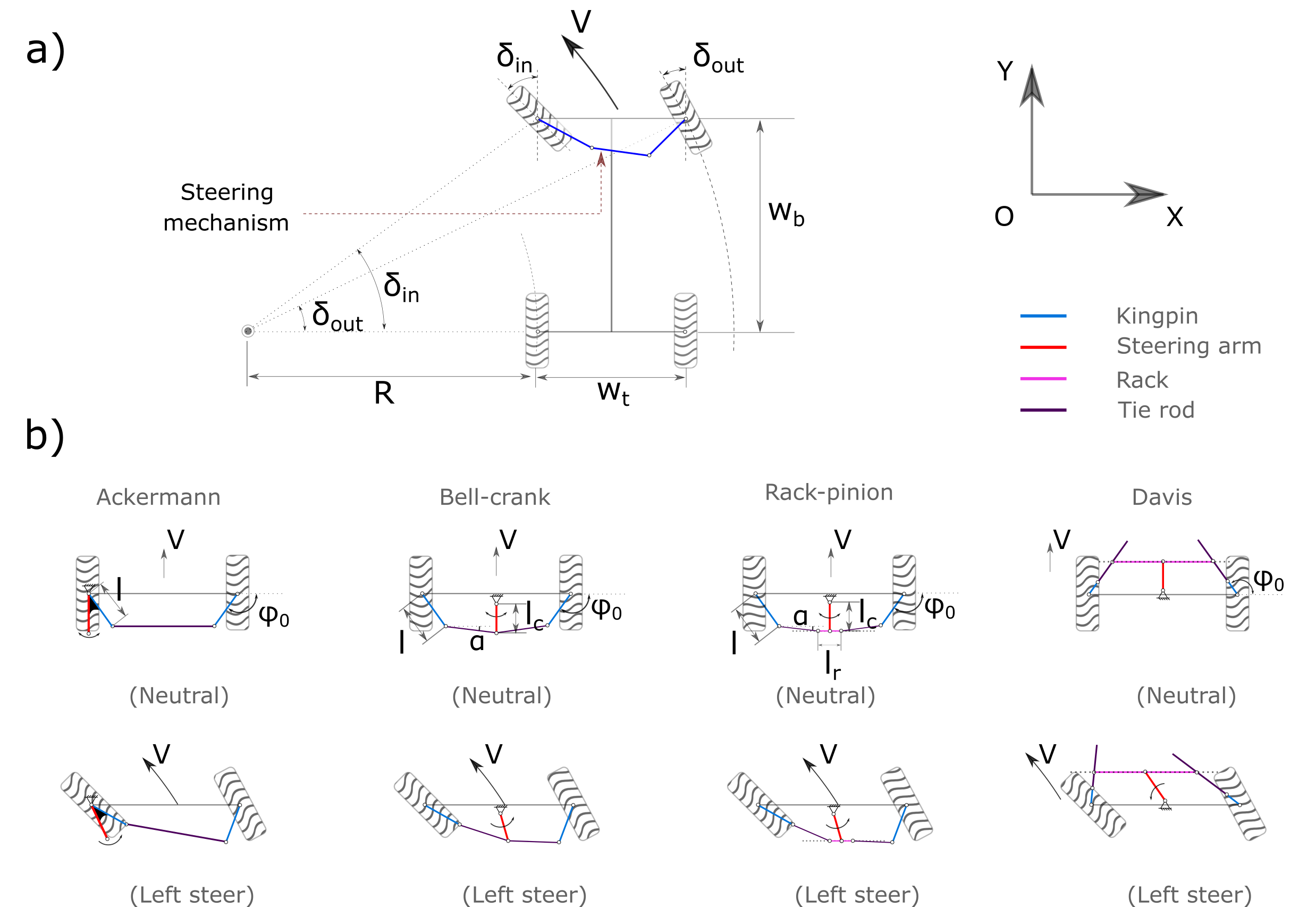
Fig. 22.11 Car steering schematic. a) Turning geometry; b) Four different steering mechanisms.
The generally used Ackermman steering mechanism (See Fig. 22.11 b) is a symmetric planar four-bar linkage. The steering arm, which rigidly connects but not limited to the left kingpin, will transmit the direct steering input of steering wheel to the two front steerable wheels via the trapezoid four-bar linkage. The Ackermann steering geometry is known to be simple and easy for calculation. But it is not always practically possible to implement. Alternatively, there are other steering mechanisms such as bell-crank (also called central-lever [7]), rack-pinion, and davis proposed.
For instance, in a bell-crank steering system, the steering arm rotates, pushing the shared ends of the tie rods to move left or right. This in turn will cause the wheel to turn due to the steering linkages. Bell-crank steering has been reported [7] that is common to wheeled tractors, ATVs, etc.
Regarding the Rack-pinion steering mechanism, the pinion is used to transmit the angular motion of the steering arm into the translational or linear motion of the rack. Rack-pinion steering mechanism is most commonly used to passenger cars [9].
Davis steering mechanism [10] is an exact steering mechanism but is seldom used in practice. It has two sliding pairs in-between the tie rod and the bar. The tie rods are only allowed to move in the direction of the its length. The main disadvantage of the Davis steering is the wear problem of the sliding pairs.
22.3.1. Geometrical parameters
As can be seen from Fig. 22.11 b), all the steering mechanisms share the common parameters of \(\phi_{0}\) and \(gear\). The meaning of these parameters have been described in Table 22.1 as shown below. It can be noticed that the number of independent geometrical parameters varies in terms of the steering mechanisms. For example, there are only one independent parameter of \(\phi_{0}\) needed for Davis steering, and two parameters of \(\phi_{0}\) and \(l\) for Ackermann steering to define the steering geometry. The steering parameters as listed in Table 22.1 are default and optimal. They were selected from [7], [8], [11] and [12].
Parameter |
Unit |
Description |
Ackermann |
BellCrank |
RackPinion |
Davis |
\(\phi_{0}\) |
rad |
Angle between kingpin direction and X axis |
\(\frac{-115}{180}\pi\) |
\(\frac{-108}{180}\pi\) |
\(\frac{-108}{180}\pi\) |
\(\frac{104}{180}\pi\) |
\(l\) |
\(\frac{1}{W_t}\) |
kingpin length |
0.16 |
0.14 |
0.14 |
– |
\(\alpha\) |
rad |
Angle between tie rod and X axis |
– |
0.0 |
0.0 |
– |
\(l_c\) |
\(\frac{1}{W_t}\) |
Steering arm length |
– |
1.0 |
1.0 |
– |
\(l_r\) |
\(\frac{1}{W_t}\) |
Rack or bar length |
– |
– |
0.25 |
– |
gear |
– |
Steering wheel gear ratio |
1.0 |
1.0 |
1.0 |
1.0 |
side |
– |
Side of steering arm positioned |
0 |
– |
– |
– |
In Table 22.1, "-" indicates that is not applicable.
The users can build their own desired steering geometry using the customized steering geometry parameters. For instance,
auto steerParams = new agxVehicle::SteeringParameters();
// The different values of parameters from the default are prescribed.
steerParams->phi0 = agx::degreesToRadians(-115);
steerParams->l = 0.16;

auto ackermann = new agxVehicle::Ackermann( leftWheel, rightWheel, steerParams);
sim->add( ackermann );
Once the steering mechanism is active, the range of the maximum allowed turning angle according to the geometrical configuration of the steering mechanism will be enabled automatically. This range should not be modified or disabled by the user. However, the user can access the maximum allowed steering angle using the getMaximumSteeringAngle() method.
22.3.2. Building steering
All the steering mechanisms implemented are enforced as three body constraints between each wheel body and the chassis.
The steering mechanisms can be created by simply replacing the “BellCrank” as shown below with the others such as “RackPinion”, “Davis” and “Ackermann”.
SteeringRef steeringMechanism = new agxVehicle::BellCrank( leftFrontWheel, rightFrontWheel );
sim->add( steeringMechanism );
If no SteeringParameters are assigned as an input after the “rightWheel”, the default steering parameters as listed in Table 22.1 will be used.
22.3.3. Steering manipulation
The steering can be manipulated using the setSteeringAngle() method.
class steeringListener : public agxSDK::StepEventListener
{
  public:
    steeringListener(agxVehicle::Ackerman* ackermann) :
    {
    }
    void pre(const agx::TimeStamp& t)
    {
      if (t < 1.0) {
        ackermann->setSteeringAngle(t);
      }
      else if (t <= 3.0) {
        ackermann->setSteeringAngle(1 - (t-1) / 2);
      }
      else
      {
        ackermann->setSteeringAngle(0.0);
      }
    }
Detailed C++ and python examples with the aforementioned steering mechanisms are
available in tutorials/agxVehicle/tutorial_carSteering.cpp and
python/tutorials/tutorial_carSteering.agxPy.
22.3.4. Pure Pursuit
Pure Pursuit is a geometric path tracking algorithm. Given a vehicle of some type, steering information is computed so that the vehicle should reach a target position on a path. As the vehicle moves forward, so does the target position.
The algorithm works in the following way:
Given the vehicle’s position relative to the path and a lookahead distance, find the target position further along the path
Based on curvature, compute how the vehicle should steer to land on the target position.
How well the vehicle tracks the actual path depends on the path, is it smooth or have sharp turns? The choice of lookahead value also affects the tracking. This lookahead can be a fixed value or be velocity-dependent for the vehicle.
Different kinds of vehicles have different ways to turn. The Pure Pursuit implementation
is made in a generic way so that it takes two inputs which provide abstractions for the required
functionality: agxVehicle::PurePursuit(agxVehicle::PurePursuit::SteeringInformation*, agxVehicle::PurePursuit::Path*);.
The first argument is an abstraction for the vehicle type. A specialization here can,
for example, be agxVehicle::TrackedVehicleSteeringInformation or agxVehicle::CarSteeringInformation.
For a tracked vehicle with 2 tracks, two velocities are computed, and the difference between
left- and right track speed causes the machine to turn. For a car, one value is computed
which is the steering angle.
The second argument to PurePursuit is the path representation which has an API for
computing the target position. A specialization here is the agxVehicle::LinearSegmentPath which
consists of multiple linear segments.
Note
Pure Pursuit is one possible component for vehicle motion that handles path tracking. It does not control start/stop logic or vehicle speed. For that it has to be combined with additional components or logic.
An example of how this functionality can be used can be seen in
python/tutorials/tutorial_purepursuit.agxPy which also shows how to create
and provide the vehicle control class with the correct coordinate system.