30. AGX Model: Deformable Object
Deformable object is a per vertex particle, volumetric, tetrahedron based mesh model with a set of algorithms responsible for bulk response, surface geometry, contact handling etc.
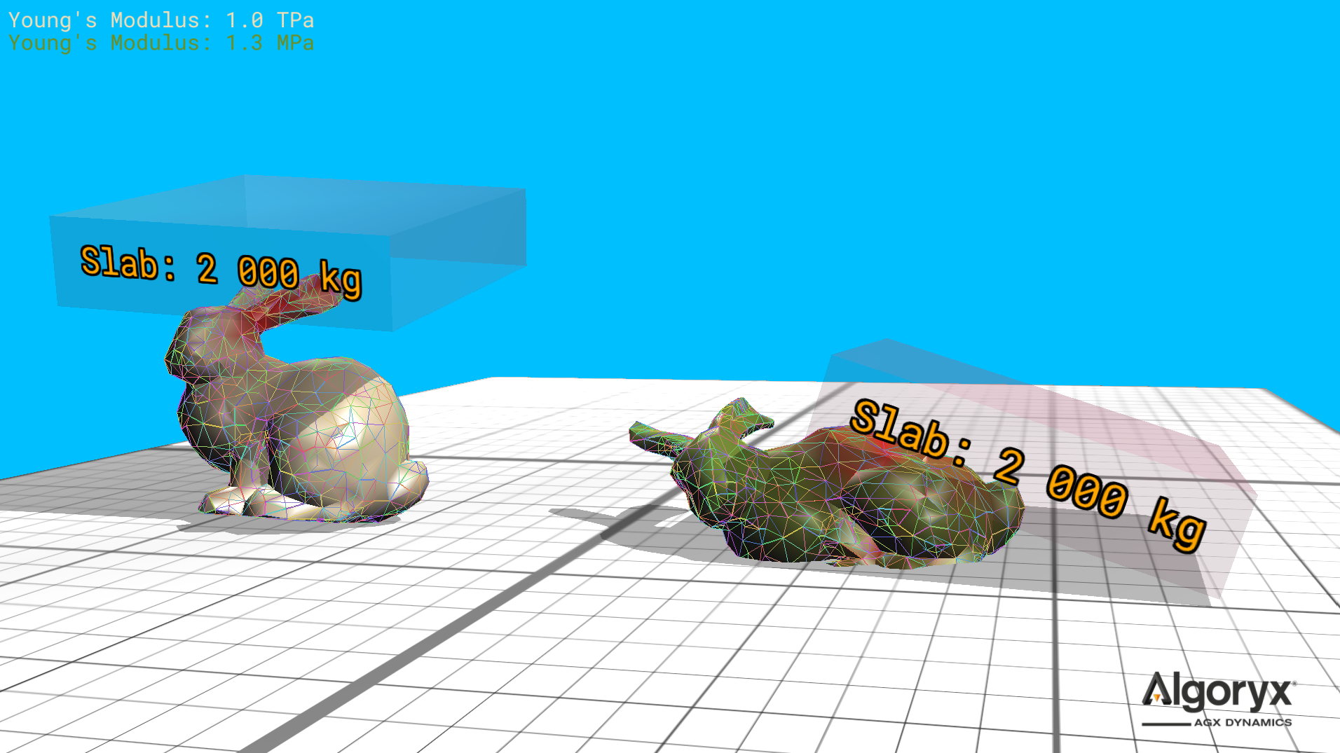
Fig. 30.1 Two metric tonne slab versus deformable bunny. The white/left one is about five times as stiff as steel (200 GPa) and doesn’t visually deform when the slab hits, while the green/right one deforms considerably with Young’s modulus at 1.3 MPa (vs. 1.0 TPa of the white).
30.1. Creating deformable objects
A deformable object is built around a volumetric tetrahedron mesh, i.e., a set of vertices and tetrahedrons defining a volume of any shape.
A tetrahedron is defined by its four vertex indices, where the cross product of the edges from the first vertex to the second and first to third points in the direction of the fourth vertex. This is important for the initial volume to be positive. If an initial volume is negative (when building the mesh), the second and third vertex indices of the tetrahedron are swapped.
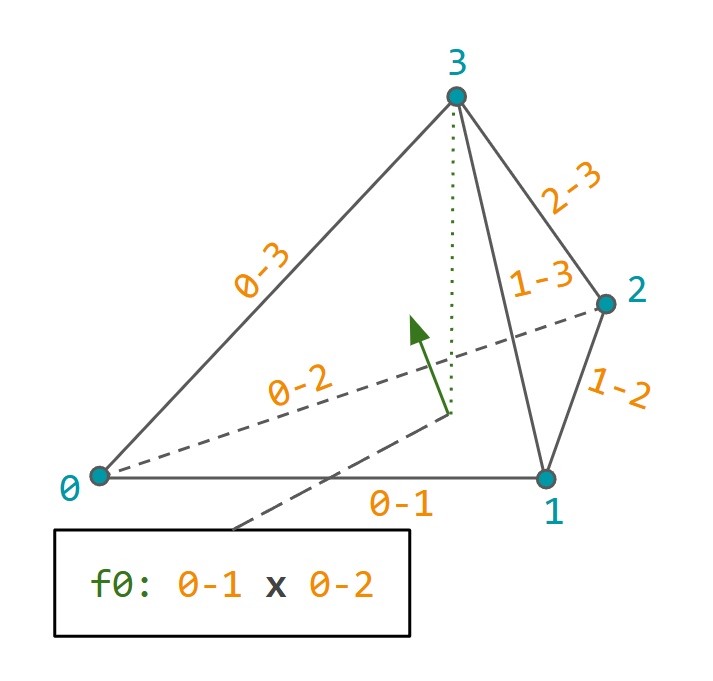
Fig. 30.2 Tetrahedron vertex indexing such that the (signed) volume is, initially, positive.
agxModel::DeformableObject supports several surface mesh formats and primitives, such as Capsule,
Sphere etc., but if the source format is unknown to AGX, it’s straightforward to create, configure and initialize
a deformable object in just a few steps.
Create an instance and access the empty mesh.
DeformableObjectRef deformable = new DeformableObject();
auto& mesh = deformable->getMesh();
Add the positions of the vertices.
for ( const auto& point : myVertexSource )
  mesh.add( { point.x, point.y, point.z } );
Define the tetrahedrons in the mesh given vertex indices.
for ( size_t ti = 0u; ti < numTetrahedrons; ++ti ) {
  auto [v0, v1, v2, v3] = myTetrahedronSource( ti );
  mesh.add( v0, v1, v2, v3 );
}
Initialize/add the deformable to a simulation.
// Will finalize the mesh and initialize everything for the simulation.
simulation->add( deformable );
// OR: Explicit initialization for more controlled error handling.
if ( !deformable->initialize() ) {
  // Error will be a warning in the log.
  std::cerr << "Unable to initialize deformable from file: \"" << filename
            << "\", see earlier warning for more information.\n";
  return;
}

simulation->add( deformable );
// OR: Even more explicit with finalizing the mesh structure explicitly
//     before initialization.

// mesh.finalize() calculates/finds the surface vertices/faces, so after
// this call it's possible to use surface elements of the mesh.
const auto meshIsValid = mesh.finalize() &&
                         !mesh.getSurfaceVertices().empty();
if ( !meshIsValid ) {
  std::cerr << "Deformable mesh initialization error - no surface elements found.\n";
  return;
}

// deformable->initialize() creates surface agxCollide::Trimesh,
// bodies/particles at each vertex, etc.
if ( !deformable->initialize() ) {
  ...
  return;
}

simulation->add( deformable );
So (mesh) finalize is calculating/finding the surface elements (vertices and faces) of the mesh, (deformable) initialize is creating bodies/particles, geometry and constraints, and (simulation) add is doing both, if not already done, and propagates all parts of the deformable to the simulation.
30.1.1. Sphere
Create a tetrahedron mesh approximating a sphere. With higher resolution, more vertices and tetrahedrons are created.
Resolution 1.0 is very high and 0.2 is low.
auto sphere = DeformableObject::create( /* type */ DeformableObject::Sphere,
                                        /* radius */ 0.5,
                                        /* resolution */ 0.55,
                                        /* properties */ new BeamModelProperties( 2.0E9, 0.45 ) );
sphere->setPosition( -40, 0, 0.5 );
simulation->add( sphere );
Argument |
Description |
Default |
|---|---|---|
radius |
Sphere radius. |
|
resolution |
Mesh resolution (> 0, where |
|
properties |
Bulk material parameters ( |
|
vertexMergeDistance |
Minimum distance before two vertices are considered identical. |
|
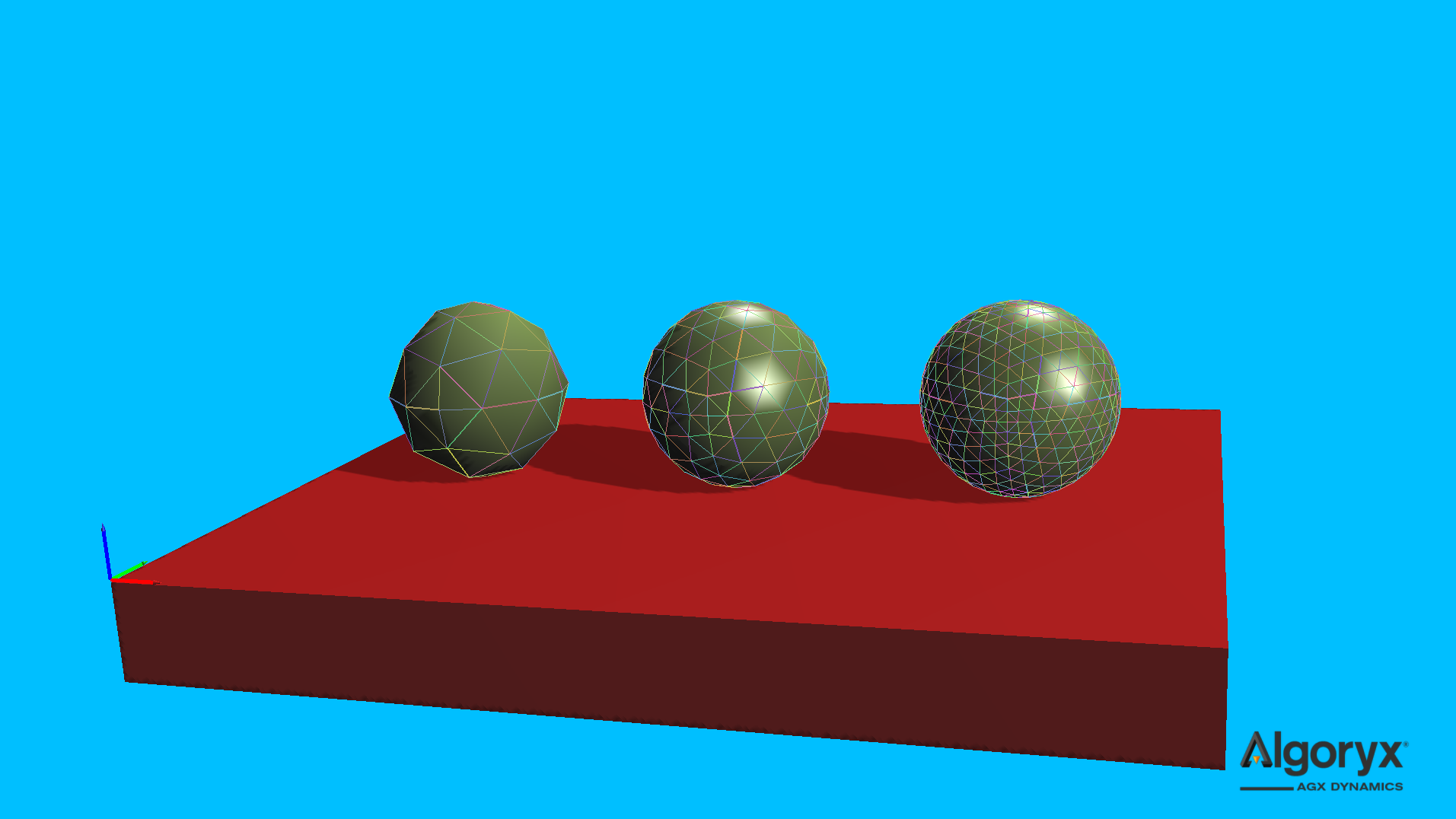
Fig. 30.3 Unit agxModel::DeformableObject::Sphere with resolutions (left to right) 0.2, 0.5 and 1.0.
30.1.2. Box
Create a tetrahedron mesh box given its half extents.
auto box = DeformableObject::create( /* type */ DeformableObject::Box,
                                     /* halfExtents */ { 0.5, 1.0, 0.75 } );
box->setPosition( -30, 0, 0.75 );
simulation->add( box );
Argument |
Description |
Default |
|---|---|---|
halfExtents |
Half extents of the box ( |
|
properties |
Bulk material parameters ( |
|
vertexMergeDistance |
Minimum distance before two vertices are considered identical. |
|
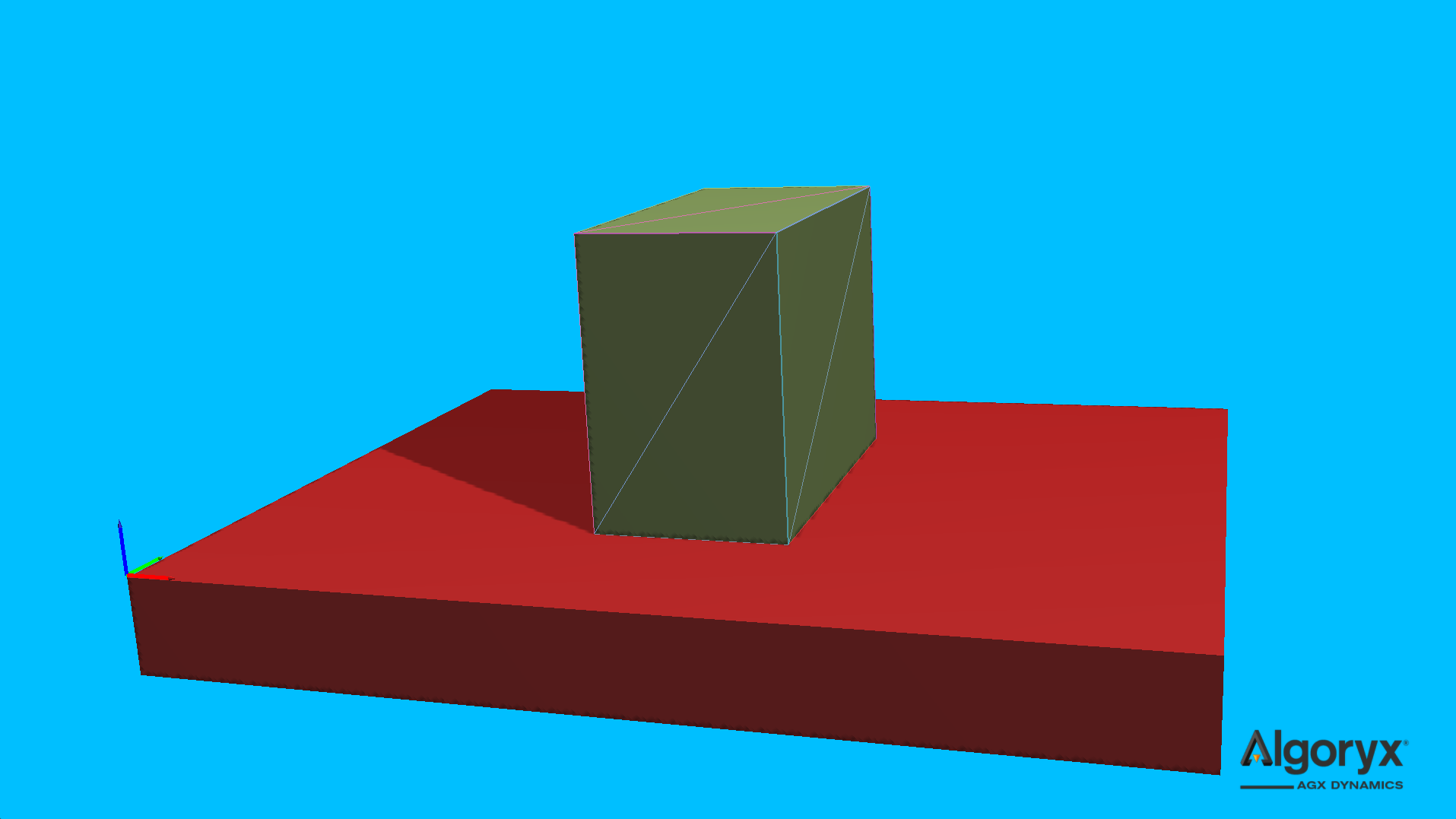
Fig. 30.4 agxModel::DeformableObject::Box of six tetrahedrons.
30.1.3. Cylinder
Create a tetrahedron mesh cylinder centered at the origin with its axis along the y axis.
auto cylinder = DeformableObject::create( /* type */ DeformableObject::Cylinder,
                                          /* radius */ 0.35,
                                          /* length */ 1.0,
                                          /* resolution */ 0.4,
                                          /* properties */ new BeamModelProperties( 6.0E5, 0.35 ) );
cylinder->setPosition( -20, 0, 0.35 );
simulation->add( cylinder );
Argument |
Description |
Default |
|---|---|---|
radius |
Cylinder radius. |
|
length |
Cylinder length. |
|
resolution |
Mesh resolution (> 0, where |
|
properties |
Bulk material parameters ( |
|
vertexMergeDistance |
Minimum distance before two vertices are considered identical. |
|
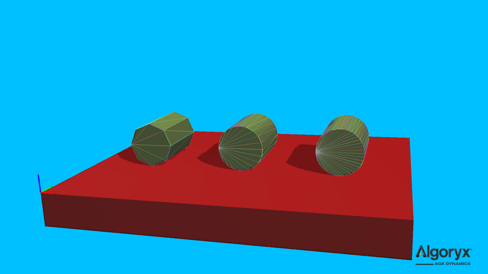
Fig. 30.5 Unit agxModel::DeformableObject::Cylinder with resolutions (left to right) 0.2, 0.5 and 1.0.
30.1.4. Capsule
Create a tetrahedron mesh capsule centered at the origin with its axis along the y axis.
auto capsule = DeformableObject::create( /* type */ DeformableObject::Capsule,
                                         /* radius */ 0.45,
                                         /* length */ 1.0,
                                         /* resolution */ 0.7,
                                         /* properties */ new BeamModelProperties( 3.0E5, 0.15 ) );
capsule->setPosition( -10, 0, 0.45 );
simulation->add( capsule );
Argument |
Description |
Default |
|---|---|---|
radius |
Capsule radius. |
|
length |
Capsule length. |
|
resolution |
Mesh resolution (> 0, where |
|
properties |
Bulk material parameters ( |
|
vertexMergeDistance |
Minimum distance before two vertices are considered identical. |
|
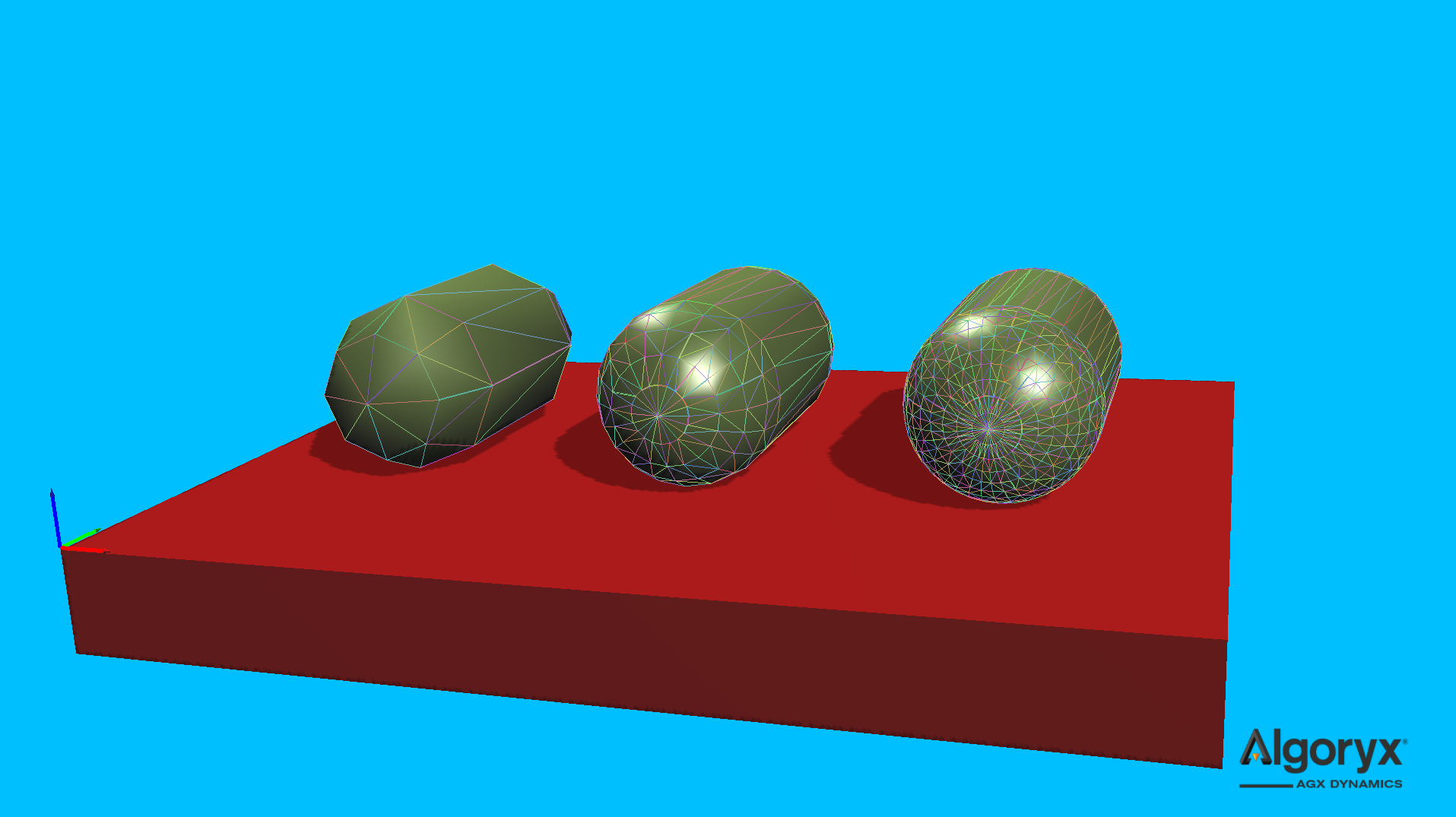
Fig. 30.6 Unit agxModel::DeformableObject::Capsule with resolutions (left to right) 0.2, 0.5 and 1.0.
30.1.5. Cone
Create a tetrahedron mesh cone aligned with the y axis and centered at the bottom.
auto cone = DeformableObject::create( /* type */ DeformableObject::Cone,
                                      /* topRadius */ 0.06,
                                      /* bottomRadius */ 0.25,
                                      /* height */ 0.8,
                                      /* resolution */ 0.45,
                                      /* properties */ new BeamModelProperties( 1.0E5, 0.35 ) );
cone->setPosition( 0, 0, 0.25 );
simulation->add( cone );
Argument |
Description |
Default |
|---|---|---|
topRadius |
Radius at the top of the cone (>= 0.0). |
|
bottomRadius |
Radius at the bottom of the cone (> 0.0). |
|
height |
Cone height (> 0.0). |
|
resolution |
Mesh resolution (> 0, where |
|
properties |
Bulk material parameters ( |
|
vertexMergeDistance |
Minimum distance before two vertices are considered identical. |
|
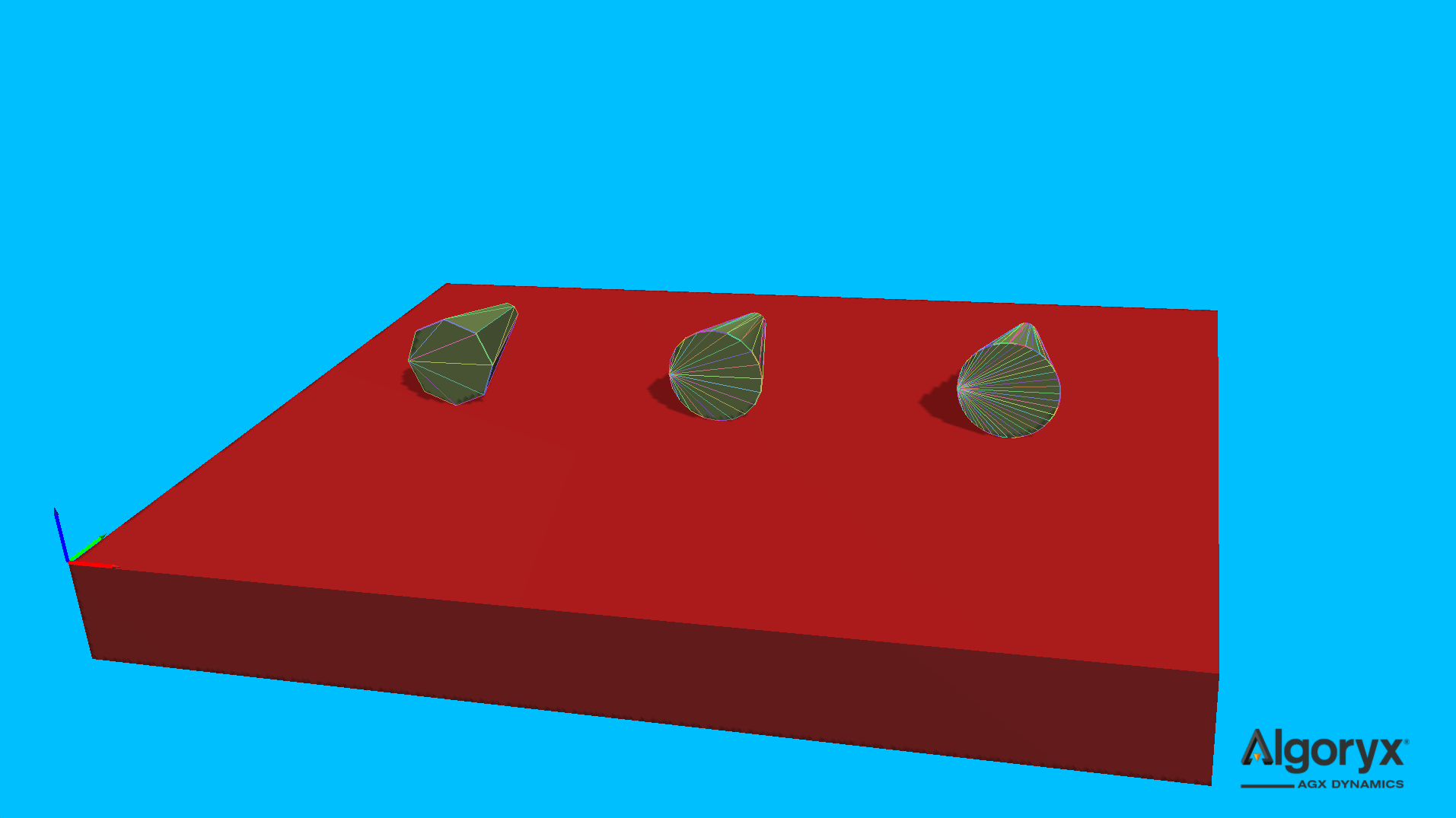
Fig. 30.7 agxModel::DeformableObject::Cone with resolutions (left to right) 0.2, 0.5 and 1.0.
30.1.6. Rectangular beam
Create a segmented rectangular beam between two points. This overload mirrors agxModel::Beam::create,
but is constrained to be a rectangular model.
auto rectangularBeam = DeformableObject::create( /* type */ DeformableObject::RectangularBeam,
                                                 /* startPosition */ { 0.0, -1.0, 0.0 },
                                                 /* endPosition */ { 0.0, 1.0, 0.0 },
                                                 /* width */ 1.0,
                                                 /* height */ 2.0 * 0.75,
                                                 /* numSegments */ 8u,
                                                 /* properties */ new BeamModelProperties( 7.0E12,
                                                                                           0.33 ) );
rectangularBeam->setPosition( 0, 0, 0.75 );
simulation->add( rectangularBeam );
Argument |
Description |
Default |
|---|---|---|
startPosition |
Beam start position. |
|
endPosition |
Beam end position. |
|
width |
Rectangular beam width. |
|
height |
Rectangular beam height. |
|
numSegments |
Number of segments along the beam (must be > 0). |
|
properties |
Bulk material parameters ( |
|
worldUpAxis |
World up axis the beam should align with. |
|
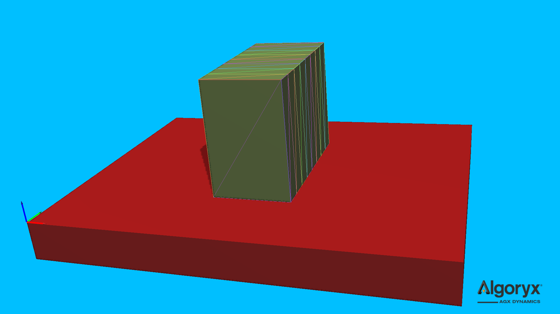
Fig. 30.8 agxModel::DeformableObject::RectangularBeam with 8 connected “box” segments.
30.1.7. Surface
Create a volumetric deformable from a heightfield by extending the surface below its lowest point by a given base thickness. The heightfield data is copied.
const auto maxHeight = 0.3;
std::array iRes = { 10u, 10u };
std::array dRes = { (agx::Real)iRes[ 0 ], (agx::Real)iRes[ 1 ] };
agx::RealVector heights( iRes[ 0 ] * iRes[ 1 ], 0.0 );
for ( auto x = 0u; x < iRes[ 0 ]; ++x ) {
  for ( auto y = 0u; y < iRes[ 1 ]; ++y ) {
    const auto dx = (agx::Real)x - 0.5 * ( dRes[ 0 ] - 1.0 );
    const auto dy = (agx::Real)y - 0.5 * ( dRes[ 1 ] - 1.0 );
    const auto e = -(
        dx * dx / ( 0.4 * dRes[ 0 ] * dRes[ 0 ] ) +
        dy * dy / ( 0.4 * dRes[ 1 ] * dRes[ 1 ] )
      );
    heights[ x * iRes[ 0 ] + y ] = maxHeight * std::exp( e );
  }
}

auto surface = DeformableObject::create( /* type */ DeformableObject::Surface,
                                         /* heightfield */ new agxCollide::HeightField( iRes[ 0 ],
                                                                                        iRes[ 1 ],
                                                                                        1.0,
                                                                                        1.0,
                                                                                        heights ),
                                         /* baseThickness */ 0.2,
                                         /* properties */ new BeamModelProperties( 4.0E5, 0.1 ) );
surface->setPosition( 10, 0, 0.2 );
simulation->add( surface );
Argument |
Description |
Default |
|---|---|---|
heightfield |
Heightfield instance with surface data (data is copied). |
|
baseThickness |
Additional thickness (>= 0.0) below the lowest height in the heightfield. |
|
properties |
Bulk material parameters ( |
|
vertexMergeDistance |
Minimum distance before two vertices are considered identical. |
|
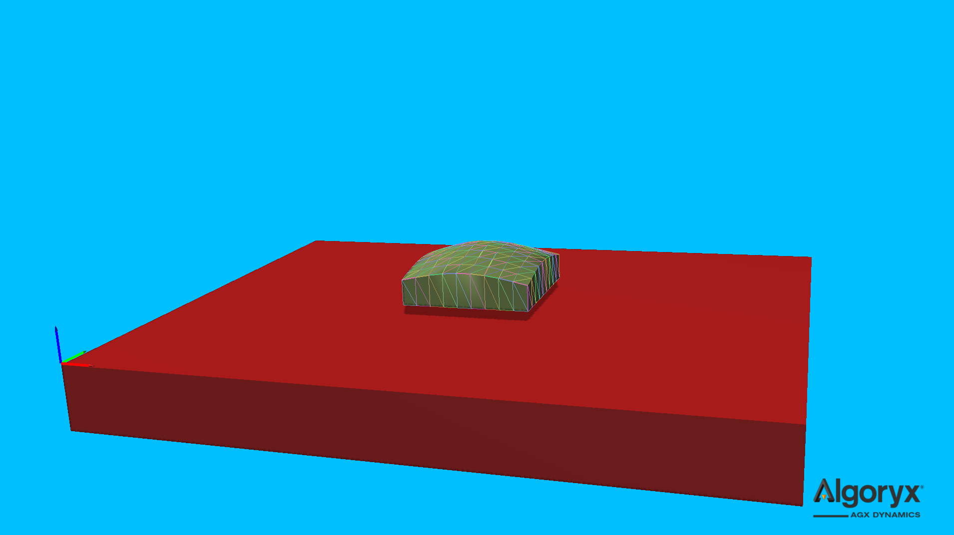
Fig. 30.9 agxModel::DeformableObject::Surface given a 10x10 grid and base thickness 0.2.
30.1.8. Convex mesh
Create a deformable from a convex surface mesh source file, instance or mesh data. If the given surface mesh isn’t convex it’s likely the 3D mesh to extend beyond the surface of the input mesh.
The tetrahedron mesh is built from the surface mesh by calculating the centroid (\(v_c\)) of the given mesh, i.e.,
where \(N\) is the number of surface vertices and the tetrahedron mesh will have \(N+1\) vertices where \(v_c\) is the last and only internal vertex. \(v_c\) is then connected with each surface triangle/face of the convex mesh.
Note
Any mesh instance and/or data passed to agxModel::DeformableObject::create( agxModel::DeformableObject::ConvexMesh, ... )
is copied, so it’s safe to destroy or reuse the instance/data afterwards.
// Reading cone.obj as a generic trimesh even though we know it's convex.
using agxUtil::TrimeshReaderWriter::createTrimesh;
agxCollide::TrimeshRef trimeshCone = createTrimesh( "models/cone.obj",
                                                    agxCollide::Trimesh::REMOVE_DUPLICATE_VERTICES,
                                                    agx::Matrix3x3{ agx::Vec3{ 1.5 } } );
if ( trimeshCone != nullptr ) {
  // Create a deformable given the mesh instance.
  BeamModelPropertiesRef coneProperties = new BeamModelProperties( 1.0E5, 0.12 );
  auto cone = DeformableObject::create( DeformableObject::ConvexMesh,
                                        trimeshCone,
                                        coneProperties );
  cone->setPosition( 38.5, 0, 0.75 );
  simulation->add( cone );

  // Reducing the number of vertices of the initial cone mesh.
  agx::Vec3Vector reducedVertices;
  agx::UInt32Vector reducedTriangles;
  agxUtil::reduceMesh( trimeshCone->getMeshData()->getVertices(),
                       trimeshCone->getMeshData()->getIndices(),
                       reducedVertices,
                       reducedTriangles,
                       0.22,
                       7.0 );

  // Create another cone with the data from the vertex reduction algorithm.
  auto reducedCone = DeformableObject::create( DeformableObject::ConvexMesh,
                                               reducedVertices,
                                               reducedTriangles,
                                               coneProperties,
                                               8.0E-3 );
  reducedCone->setPosition( 41.5, 0, 0.75 );
  simulation->add( reducedCone );
}
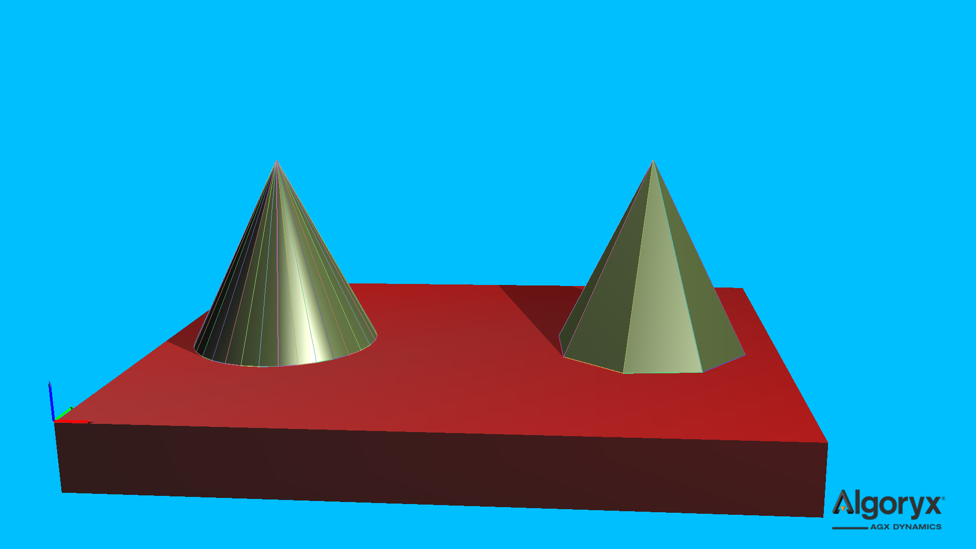
Fig. 30.10 agxModel::DeformableObject::ConvexMesh of read “cone.obj” (left) and its vertex reduced variant (right).
30.1.9. TetGen
Create a deformable from TetGen files. The import expects both .node (vertex positions) and .ele
(tetrahedron definitions). The filename argument is the common base name including path.
const auto filename = std::string( "path/to/tetgenmeshes/cow.1" );
auto cow = DeformableObject::create( /* type */ DeformableObject::TetGen,
                                     /* common .ele and .node name */ filename,
                                     /* scale */ agx::Vec3{ 0.3 },
                                     /* properties */ new BeamModelProperties( 1.0E9, 0.45 ) );
cow->setRotation( agx::Quat::rotate( agx::Vec3::Y_AXIS(), agx::Vec3::Z_AXIS() ) *
                  agx::Quat::rotate( agx::Vec3::X_AXIS(), -agx::Vec3::Y_AXIS() ) );
cow->setPosition( 20, 0, 1.1 );
simulation->add( cow );
Argument |
Description |
Default |
|---|---|---|
filename |
Common base name (expects |
|
scale |
Scale applied to the imported model ( |
|
properties |
Bulk material parameters ( |
|
vertexMergeDistance |
Minimum distance before two vertices are considered identical. |
|
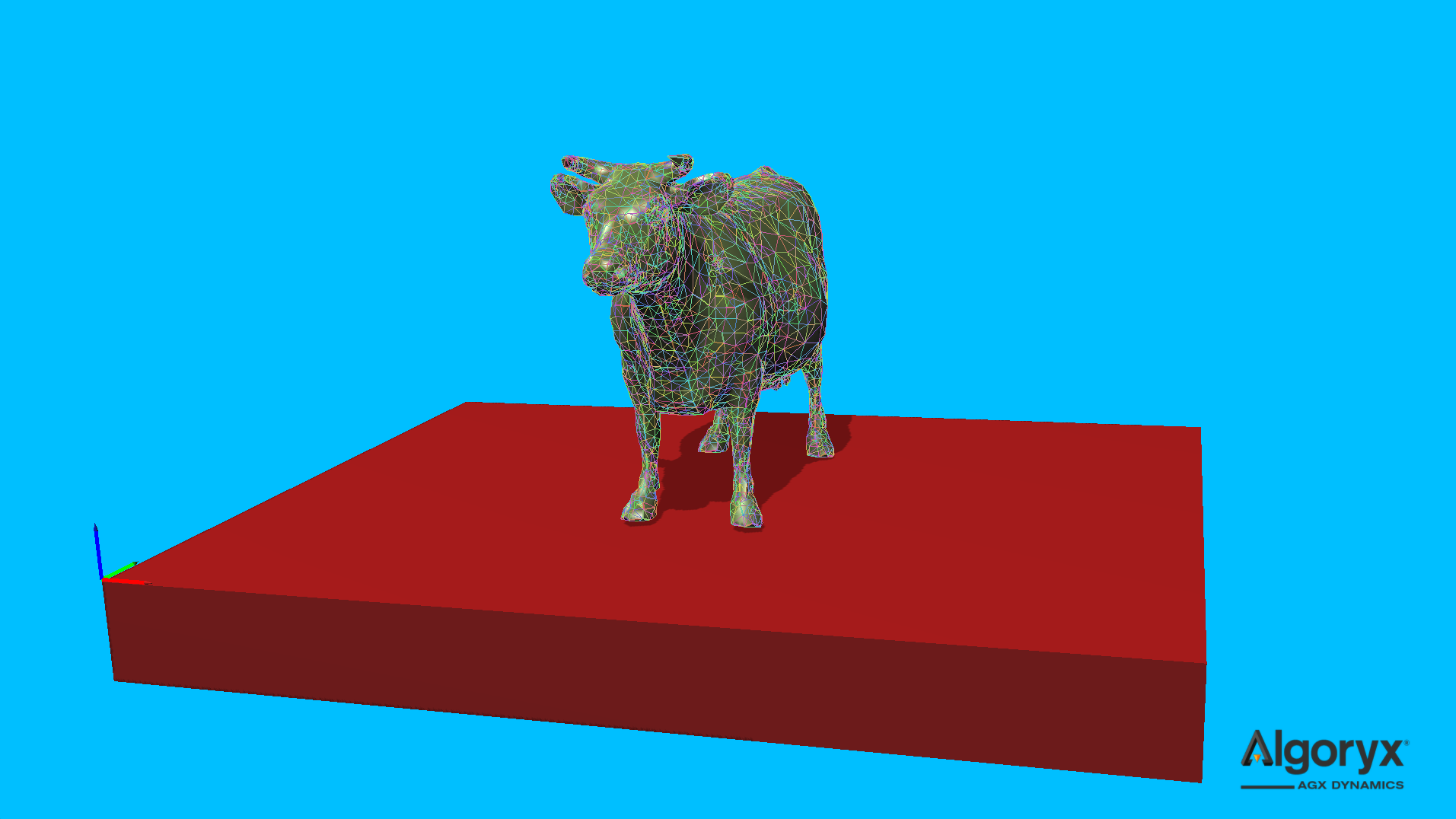
Fig. 30.11 TetGen generated tetrahedron mesh.
30.1.10. Tetrahedron
Create a single tetrahedron from four vertex positions.
auto tetrahedron = DeformableObject::create( /* type */ DeformableObject::Tetrahedron,
                                             /* vertices */
                                             {
                                               agx::Vec3{ -0.50,  0.00, 0.00 },
                                               agx::Vec3{  0.50, -0.50, 0.00 },
                                               agx::Vec3{  0.50,  0.50, 0.00 },
                                               agx::Vec3{  0.25,  0.00, 0.50 },
                                             },
                                             /* properties */ new BeamModelProperties( 1.0E7, 0.25 ) );
tetrahedron->setPosition( -50, 0, 0 );
simulation->add( tetrahedron );
Argument |
Description |
Default |
|---|---|---|
positions |
Four initial vertex positions ( |
|
properties |
Bulk material parameters ( |
|
vertexMergeDistance |
Minimum distance before two vertices are considered identical. |
|
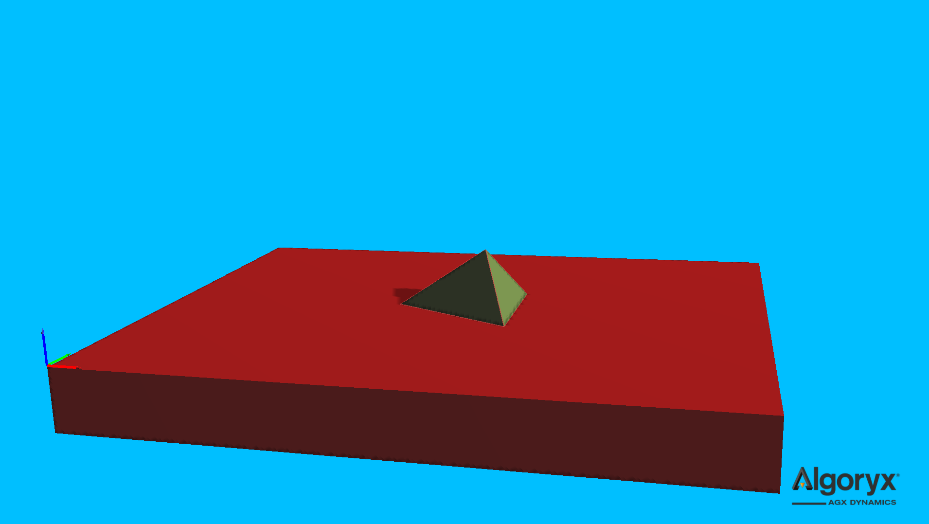
Fig. 30.12 Not very useful single tetrahedron model.
30.2. Using deformable objects
A newly (successfully) initialized deformable object has a well defined transform, enabling for
initial positioning and orientation to be assigned for the common frame (agxSDK::Assembly)
of the deformable. But at any simulation time after the deformable has been simulated, the common
frame is still fixed where it was initialized, while the vertices has moved in that frame and relative
to each other (deformation). See Vertex elements for more information
about the internal state of the deformable.
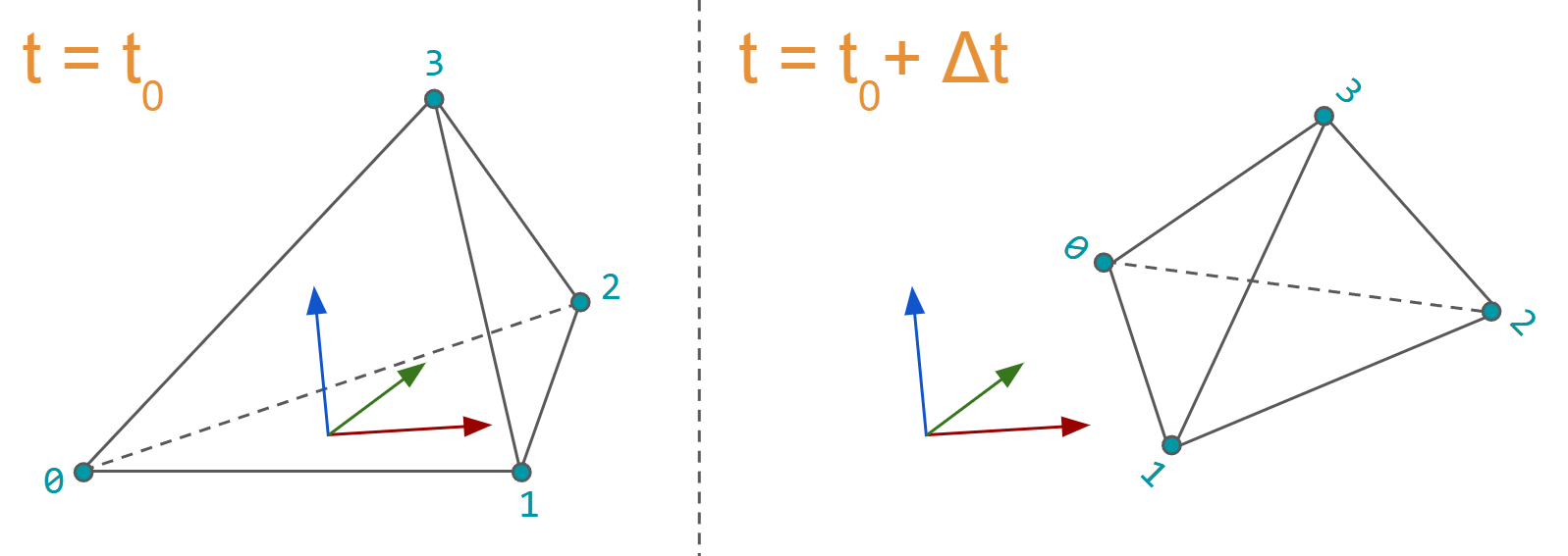
Fig. 30.13 A deformable at initialization time \(t_0\) has a well defined overall transform, while deformations and vertex movements at a future time \(t_0 + \Delta t\) makes the common frame less intuitive but it’s probably not of importance.
The mesh and its data is accessed through mesh elements, where an element is a lightweight structure containing an integer, a pointer (to its data) and an API. The different elements of the mesh represents the data for vertices (surface and internal), edges, faces (surface and internal) and tetrahedrons.
30.2.1. Vertex elements
Each vertex element (agxModel::DVertexElement) in the mesh represents three different
positions and references an agx::RigidBody instance (as 3 DOF particle) defining the movement
of it. The different positions are:
Initial: Initial position, i.e., the one when added to the mesh initially, given in the frame of the deformable. This position is often mostly used internally to track the deformable’s displacement field but can also be used to find particles in the mesh when the form and positions often is know in this initial state.
Local: Current position of the vertex given in the frame of the deformable. This is the
getPosition()of vertex elements and should be used in rendering of the deformable (Rendering (example)).World: Current position of the vertex given in the world frame. This position is updated/written when needed (e.g., before collision detection, before the solver and mesh finalization) or when the positions of the vertex bodies has been integrated. Note: Not when the transform of the deformable has been changed by the user.
const auto& mesh = deformable->getMesh();
for ( agxModel::DVertexElement vertex : mesh.getVertices() ) {
  const agx::Vec3 initPosition = vertex.getPositionInitial();
  const agx::Vec3 localPosition = vertex.getPosition();
  const agx::Vec3 worldPosition = vertex .getPositionWorld();
  // Note that, during runtime:
  //   worldPosition == deformable->getTransform().transformPoint(localPosition)
}
30.2.2. Surface vertex elements
The surface vertex (agxModel::DSurfaceVertexElement) elements are a subset of the
Vertex elements (or complete set in some cases) that lives on and defines the
surface of a deformable object. The surface vertices has their own elements buffer so their indices may be used
to manage, e.g., (vertices of) a surface mesh. The API matches the Vertex elements
except that it’s possible to convert a surface vertex element to a vertex element:
const auto& mesh = deformable->getMesh();
// NOTE: getSurfaceVertices()            vs getVertices() and
//       agxModel::DSurfaceVertexElement vs agxModel::DVertexElement.
for ( agxModel::DSurfaceVertexElement surfaceVertex : mesh.getSurfaceVertices() ) {
   // "cast" to vertex element - surfaceVertex and asVertex shares data
   // but normally have different indices.
   agxModel::DVertexElement asVertex = surfaceVertex.toVertex();

   // These are identical, they share the same data in the buffers.
   assert( surfaceVertex.getPositionInitial() == asVertex.getPositionInitial() );
   assert( surfaceVertex.getPosition() == asVertex.getPosition() );
   assert( surfaceVertex.getPositionWorld() == asVertex.getPositionWorld() );
   assert( surfaceVertex.getRigidBody() == asVertex.getRigidBody() );

   // Assume these two indices doesn't match.
   const auto surfaceVertexIndex = surfaceVertex.index();
   const auto asVertexIndex = asVertex.index();
}
30.2.3. Edge elements
An edge (agxModel::DEdgeElement) represents the line between two vertices in the mesh. If e_ij is the
edge between vertex indices i and j, then its opposite e_ji is also stored by the mesh.
The following example finds the edge closest to a point (in world), skipping every opposite edge by only testing edges when the first vertex index is less than the second vertex index.
DEdgeElement findClosestEdge( agx::Vec3 point, const DeformableObject& deformable )
{
  auto& mesh = deformable.getMesh();
  DEdgeElement closestEdge{};
  agx::Real minDistanceSquared = agx::Infinity;
  for ( DEdgeElement edge : mesh.getEdges() ) {
    // Skip the "other" version of the edge where the vertex
    // index of the second vertex is less than that of the first.
    if ( edge.getVertices()[ 1 ].index() < edge.getVertices()[ 0 ].index() )
      continue;

    const auto toEdgeDistanceSquared = edge.findDistanceSquared( point );
    if ( toEdgeDistanceSquared < minDistanceSquared ) {
      closestEdge = edge;
      minDistanceSquared = toEdgeDistanceSquared;
    }
  }

  return closestEdge;
}
30.2.4. Face elements
A face element (agxModel::DFaceElement) represents a triangle in the tetrahedron mesh. A face with an invalid
“opposite” version of itself is on the surface of the deformable object.
See Surface face elements and Rendering (example) for more convenient ways of accessing the surface mesh, here is an example of how to collect all surface faces and calculating the total surface area (in more and less convenient ways).
DFaceElementStorage findSurface( const DeformableObject& deformable )
{
  const auto& mesh = deformable.getMesh();

  DFaceElementStorage surfaceFaces;
  for ( DFaceElement face : mesh.getFaces() ) {
    // This face is on the surface if it doesn't have an
    // opposite face (sitting on a neighboring tetrahedron).
    const auto isSurfaceFace = !face.getOppositeFace().valid();
    assert( isSurfaceFace == face.isSurface() );

    if ( isSurfaceFace )
      surfaceFaces.push_back( face );
  }

  return surfaceFaces;
}

agx::Real calculateSurfaceArea( const DeformableObject& deformable )
{
  DFaceElementStorage surfaceFaces = findSurface( deformable );
  agx::Real surfaceArea1 = 0.0;
  agx::Real surfaceArea2 = 0.0;
  agx::Real surfaceArea3 = 0.0;
  for ( auto surfaceFace : surfaceFaces ) {
    surfaceArea1 += surfaceFace.calculateArea();
    surfaceArea2 += agxModel::utils::calculateArea( surfaceFace.getVertices()[ 0 ].getPosition(),
                                                    surfaceFace.getVertices()[ 1 ].getPosition(),
                                                    surfaceFace.getVertices()[ 2 ].getPosition() );
    // The three vertices are individually the first vertex
    // in each edge for the face/triangle.
    const auto edges = surfaceFace.getEdges();
    surfaceArea3 += agxModel::utils::calculateArea( edges[ 0 ].getVertices()[ 0 ].getPosition(),
                                                    edges[ 1 ].getVertices()[ 0 ].getPosition(),
                                                    edges[ 2 ].getVertices()[ 0 ].getPosition() );
  }

  std::cout << agx::String::format( "%s:\n"
                                    "    surfaceArea1 = %.16f\n"
                                    "    surfaceArea2 = %.16f\n"
                                    "    surfaceArea3 = %.16f\n\n",
                                    deformable.getName(),
                                    surfaceArea1,
                                    surfaceArea2,
                                    surfaceArea3 );

  return surfaceArea1;
}
Calling calculateSurfaceArea for the three spheres in the figure in Sphere
prints:
agxModel::DeformableObject::Sphere:
    surfaceArea1 = 2.8801337481867670
    surfaceArea2 = 2.8801337481867670
    surfaceArea3 = 2.8801337481867670

agxModel::DeformableObject::Sphere:
    surfaceArea1 = 3.0702742615382190
    surfaceArea2 = 3.0702742615382190
    surfaceArea3 = 3.0702742615382190

agxModel::DeformableObject::Sphere:
    surfaceArea1 = 3.1199314141591286
    surfaceArea2 = 3.1199314141591286
    surfaceArea3 = 3.1199314141591286
30.2.5. Surface face elements
A surface face element (agxModel::DSurfaceFaceElement) is a subset of the Face elements
that lie on the surface of the deformable object. Like surface vertices, surface faces have their own elements buffer
and therefore their indices generally differ from its agxModel::DFaceElement.
Below is an example showing how to create a rigid body version of a deformable. The rigid body version contains a trimesh shape of the deformable surface.
Note
The vertex ordering of the faces are clockwise which is the common face/triangle ordering of 3D meshes. The common vertex ordering of surface meshes, such has collision or rendering meshes, is counterclockwise and to transform between the two, one swap vertex two and three of the triangle (as shown in the example below).
/**
Creates a trimesh rigid body given a deformable object.
*/
agx::RigidBodyRef createRigidBody( const DeformableObject& deformable )
{
  const auto& mesh = deformable.getMesh();
  const auto& surfaceVertexElements = mesh.getSurfaceVertices();
  const auto& surfaceFaceElements = mesh.getSurfaceFaces();

  // Collect the surface vertices of the deformable as vertices
  // of the rigid trimesh.
  agx::Vec3Vector trimeshVertices;
  trimeshVertices.reserve( surfaceVertexElements.size() );
  for ( const auto surfaceVertex : surfaceVertexElements )
    trimeshVertices.push_back( surfaceVertex.getPosition() );

  agx::UInt32Vector trimeshTriangles;
  trimeshTriangles.reserve( 3u * trimeshVertices.size() );
  for ( const auto surfaceFace : surfaceFaceElements ) {
    const auto surfaceVertices = surfaceFace.getVertices();
    trimeshTriangles.push_back( surfaceVertices[ 0 ].index() );
    // Note that we swap vertex two and three here to get a counterclockwise,
    // AGX collision mesh supported, version of the deformable surface.
    trimeshTriangles.push_back( surfaceVertices[ 2 ].index() );
    trimeshTriangles.push_back( surfaceVertices[ 1 ].index() );
  }

  agxCollide::TrimeshRef trimesh = new agxCollide::Trimesh( &trimeshVertices,
                                                            &trimeshTriangles,
                                                            "From agxModel::DeformableObject" );
  agx::RigidBodyRef rigidVersion = new agx::RigidBody( new agxCollide::Geometry( trimesh ) );
  // ...
  return rigidVersion;
}
30.2.6. Tetrahedron elements
A tetrahedron element (agxModel::DTetrahedronElement) represents a single volumetric cell of the deformable mesh. It
provates access to its four Vertex elements (getVertices()), six
Edge elements (getEdges()) and four Face elements
(getFaces()).
For each tetrahedron element there is a constraint constraining its four vertices to be in the (relative) initial configuration they were given in. There’s currently no convenient way to access and/or couple the constraints with its corresponding tetrahedrons, but it is possible, here is an example:
using DeformableConstraintVisitor = std::function<void( const DTetrahedronElement&,
                                                        const ElementaryTetrahedronConstraint& )>;

void traverseConstraints( const DeformableObject& deformable,
                          DeformableConstraintVisitor visitor )
{
  // IDeformableConstraint is responsible for the constraints and is very
  // much expected to be in the deformable BUT it is implementation dependent
  // how many constraints there are. We know now that the number of constraints
  // is equal to the number of tetrahedrons in the mesh.
  auto constraints = deformable.getAlgorithm<IDeformableConstraint>();
  if ( constraints == nullptr )
    return;

  // The number of tetrahedrons and constraints are the same and the
  // constraints were created using this buffer, so they match.
  const auto& tetrahedrons = deformable.getMesh().getTetrahedrons();
  size_t tetrahedronIndex = 0u;
  constraints->traverseElementaryConstraints( [&]( const agx::ElementaryConstraint& ec )
  {
    if ( const auto tetrahedronConstraint = ec.asSafe<ElementaryTetrahedronConstraint>() )
      visitor( tetrahedrons[ tetrahedronIndex++ ], *tetrahedronConstraint );
  } );
}
30.2.6.1. Stresses
The result of the simulation of the deformable is internal stresses. Each tetrahedron provides six stress components, three normal components \([\sigma_{xx}, \sigma_{yy}, \sigma_{zz}]\), and three shear components \([\tau_{xy}, \tau_{xz}, \tau_{yz}]\).
A common scalar for visualization and engineering post-processing is the von Mises equivalent stress defined as:
where \(\sigma\) are the principal and \(\tau\) the shear stresees. If the yield strength \(\sigma_y\), or some other material/structural failure parameter is known, the von Mises stress \(\sigma_{\mathrm{vm}}\) can be used to estimate the Factor of Safety (FoS) of the object.
The FoS is a per time step indicator of margin relative to the chosen allowable, let’s use the yield strength \(\sigma_y\), then:
with interpretations:
\(\mathrm{FoS}_y > 1 \rightarrow\) below yield, i.e., in the elastic regime.
\(\mathrm{FoS}_y \approx 1 \rightarrow\) at the limit, yield somewhere.
\(\mathrm{FoS}_y < 1 \rightarrow\) plasticity would be expected in reality.
The following example is calculating the von Mises stresses and FoS per tetrahedron of a deformable (using traverseConstraints
from above):
agx::RealVector calculateVonMises( const DeformableObject& deformable )
{
  // One von Mises stress value per tetrahedron.
  agx::RealVector vmStresses;
  vmStresses.resize( deformable.getMesh().getTetrahedrons().size(), 0.0 );

  const auto vonMises = []( agx::Real s_xx,
                            agx::Real s_yy,
                            agx::Real s_zz,
                            agx::Real t_xy,
                            agx::Real t_xz,
                            agx::Real t_yz ) -> agx::Real
  {
    const auto a = 0.5 * ( ( s_xx - s_yy ) * ( s_xx - s_yy ) +
                           ( s_yy - s_zz ) * ( s_yy - s_zz ) +
                           ( s_zz - s_xx ) * ( s_zz - s_xx ) );
    const auto b = 3.0 * ( ( t_xy * t_xy ) +
                           ( t_xz * t_xz ) +
                           ( t_yz * t_yz ) );

    return std::sqrt( a + b );
  };

  traverseConstraints( deformable,
                       [&]( const DTetrahedronElement& tetrahedron,
                            const ElementaryTetrahedronConstraint& constraint )
  {
    // We expect 6 DoF or more in the constraint, otherwise it's not supported.
    if ( constraint.getNumRows() < 6u )
      return;

    const auto stresses = constraint.getCurrentForces();
    vmStresses[ tetrahedron.index() ] = vonMises( /* xx */ stresses[ 0 ],
                                                  /* yy */ stresses[ 1 ],
                                                  /* zz */ stresses[ 2 ],
                                                  /* xy */ stresses[ 3 ],
                                                  /* xz */ stresses[ 4 ],
                                                  /* yz */ stresses[ 5 ] );
  } );

  return vmStresses;
}
agx::RealVector calculateFactorOfSafety( const DeformableObject& deformable,
                                         agx::Real yieldStrength )
{
  // The von Mises stresses at the current state - normally "post" solve.
  const auto vmStresses = calculateVonMises( deformable );

  // Factor of Safety for each tetrahedron in the deformable.
  agx::RealVector fosYield;
  fosYield.resize( vmStresses.size(), 0.0 );
  // Note that FoS becomes much, much larger than one for stresses < 1 assuming
  // that the yield strength normally is a large value (related to 1.0).
  for ( size_t i = 0u; i < vmStresses.size(); ++i )
    fosYield[ i ] = yieldStrength / std::max( vmStresses[ i ], 1.0E-3 );

  return fosYield;
}
30.2.7. Rendering (example)
It’s common deformable objects are generated from local mesh data and then moved to its initial transform in world space. E.g.,
// Center in world origin.
auto box = DeformableObject::create( DeformableObject::Box,
                                     /* halfExtents */ { 1, 1, 1 } );
simulation->add( box );
box->setPosition( 1, 2, 3 );
box->setRotation( agx::Quat::rotate( agx::degreesToRadians( 45 ), agx::Vec3::Y_AXIS() ) );
and for the visuals/rendering of the deformable to be synchronized, it’s recommended to use the local vertex positions and either multiply each of them with the common frame/transform of the deformable or let the parent rendering node (if tree/graph based), carry the transform of the deformable:
void MyDeformableRenderer::update()
{
  // Let render graph node parent have the transform of the
  // deformable, the frame the vertices move in.
  const auto deformable = getDeformable();
  getParent()->setMatrix( convert( deformable->getTransform() ) );

  // The deformable vertices getPosition() are their deformed state in
  // the frame of the deformable, and since our parent shares that
  // transform we write these local positions to the vertex buffer.
  auto& renderVertexBuffer = getVertexBuffer();
  for ( const auto surfaceVertex : deformable->getMesh().getSurfaceVertices() ) {
    renderVertexBuffer[ surfaceVertex.index() ] = convert( surfaceVertex.getPosition() );
    // Equivalent without a parent:
    //   renderVertexBuffer[ surfaceVertex.index() ] =
    //     convert( surfaceVertex.getPosition() * deformable->getTransform() );
  }
}
Note
As mentioned under World positions in Vertex elements - the buffer containing the world positions of the vertices is for, performance reasons, only updated when the world positions are important for the simulation. For example before collision detection and solver, and after the transforms of the system has been integrated. So for the deformable (render) mesh to always be synchronized, the local positions of the vertices and transform of the deformable has to be used.
30.2.8. Linear- and angular velocity
A deformable object is a per-vertex particle model, meaning it does not have a single rigid body state with
a well-defined linear and angular velocity in the same way as agx::RigidBody. Assigning an angular
velocity therefore requires converting a rigid-body-like velocity field into individual vertex linear
velocities, which is sensitive to the chosen center of rotation (center of mass) and the current vertex
configuration.
The helper agxModel::DeformableObject::setRigidVelocity assigns per-vertex velocities consistent with
a rigid motion about the current center of mass:
where \(\mathbf{x}\) is the vertex world position and \(\mathbf{x}_{\mathrm{cm}}\) is the current center of mass.