26. agxTerrain
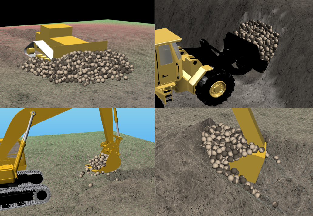
agxTerrain is a library consisting of classes that implement a deformable terrain model called agxTerrain::Terrain which is based on
a symmetric 3D grid data structure with an overlapping surface height field. It can be deformed by interacting agxTerrain::Shovel objects
performing different operations, such as digging, push/pull and grading. This can be used to model a wide variety of earthmoving
scenarios such as bulldozing, wheel loading, excavation and trenching.
The underlying terrain data model consists of a hierarchical sparse 3D grid of cells, containing terrain data such as mass and compaction.
The terrain surface is represented as a 2D height field that is updated when the underlying grid structure is changed, mainly through excavation.
Mass is moved in the terrain via interacting Shovels that converts solid cells to dynamic mass. Each shovel is defined via specifying a
top edge, a cutting edge and a cutting direction and a base Shovel body. This is used to create excavation planes around the
rigid body that generates Active Zones when moved against the terrain. These zones consists of soil wedges shapes derived from soil
mechanics theory which predicts a failure volume in the shovel/terrain intersection, which generate dynamic mass.
The dynamic mass is expressed in the form of 6-degrees of freedom soil particles with hertzian contact dynamics, Coulomb friction and rolling resistance. The dynamic soil is pushed via the shovel through kinematic coupling. A mass aggregate body is constructed in the shovel failure zones that returns a resistance force against the shovel via contacts in the soil failure plane. The dynamic soil is merged back into the terrain when approaching a steady state on the terrain surface. The number of active soil particles depends on the amount of grid points touched by the dig volume, which in turn is a function of both blade size, dig depth, terrain resolution and dig length.
openvdb, which is a library for representing large sparse 3D hierarchal voxel structures, is used for cell storage and representation.
26.1. Workflow
The main classes that the user interacts with when working with agxTerrain is as follows:
|
The deformable terrain object. |
|
Shovel object that converts solid mass in a |
|
Object that holds material properties used to characterize soil behavior such as compaction, soil particle dynamics and bulk properties. |
|
Object that holds generic terrain properties such as disable/enable for different features and locking terrain borders. |
|
Interface for controlling the soil simulation governing dynamic soil behavior. |
|
Controller for accessing and controlling the underlying terrain data on grid element level. |
The overall work flow for setting up a terrain model is as follows:
Create a agxTerrain::Terrain object from resolution data or an existing height field.
Create and configure agxTerrain::Shovel objects by specifying a shovel body, cutting edge, top edge and cutting direction.
Configure TerrainMaterial via the
loadLibraryMaterialmethod or by extracting and changing theTerrainMaterialobject.Configure Calibrate excavation resistance by configuring shovel-terrain contact material and soil properties.
Setup contact materials between the terrain and external objects.
Modify the terrain properties via the
agxTerrain::TerrainPropetiesclass.Modify the terrain grid structure using the
agxTerrain::TerrainGridControlclass.(Optional) Configure the dynamic soil.
26.2. Terrain
A agxTerrain::Terrain object can either be created using resolution data or an existing height field. The data cells in the terrain is symmetric by design which means
that the user is constrained to setting resolution and cell size to ensure that we have a valid data structure.
Creating a basic terrain using only resolution data is done by using the following constructors:
/**
Constructor. Creates a terrain object with a specific resolution of 2D grid points with elementSize as the length between them.
The terrain length in each direction thus becomes (resolution + 1) * elementSize.
\param resolutionX - The number of height points to use in the Terrain in the X-direction.
\param resolutionY - The number of height points to use in the Terrain in the Y-direction.
\param elementSize - The distance between the height points in the terrain.
\param maximumDepth - The maximum depth that the terrain can have.
*/
agxTerrain::Terrain(size_t resolutionX,
                    size_t resolutionY,
                    agx::Real elementSize,
                    agx::Real maximumDepth);
maximumDepth is the maximum depth below 0 that the terrain can have in it’s local z-direction. The elementSize sets the uniform size of
the 3D grid cells in the terrain structure. The total length of the terrain in either axis will thus become (resolutionX-1) * elementSize in either direction.
Creating a terrain object from an existing height field is done by using the following method:
/**
Creates a terrain object by using an existing height field as a basis. The height field data is copied into
the internal terrain structure. The existing height field MUST have uniform scale in X and Y axis, otherwise
the function returns nullptr.
\note The specified height field is copied and never used inside Terrain object.
\param height field - The height field object that will be used as a basis for creating
\param maximumDepth - The maximum depth of the terrain.
\return A terrain object create from the specified height field or nullptr if an invalid height field is given.
*/
agxTerrain::Terrain* agxTerrain::Terrain::createFromHeightField( agxCollide::HeightField* heightField, maximumDepth );
Warning
The specified height field must have symmetric scale. I.e. the distance between vertices in x-direction must be the same as in y-direction. An agx::LOGGER_WARNING will tell you if you have a unsymmetrical height field scale and a nullptr will be return from the function.
26.2.1. Terrain Grid Structure
The terrain data is stored underlying 3D grid structure. It is usually accessed either on the surface using 2D grid coordinates or in 3D space using full 3D grid coordinates. The data that is stored in the grid is solid mass and soil compaction.
Surface terrain data, such as terrain height, is accessed by specifying a terrain surface index, which references a single discrete surface grid point on the
terrain. The terrain surface index consists of 2D x and y coordinates with origin (x:0, y:0) in the lower leftmost gridpoint and the maximum coordinate in
the upper rightmost gridpoint ( x: resolutionX-1, y: resolutionY-1 ) in the terrain surface structure.
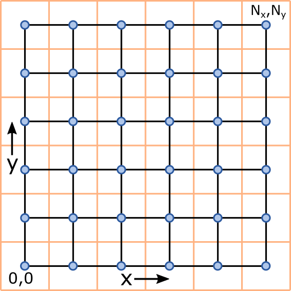
Fig. 26.1 Figure that shows the indexing and grid layout of the agxTerrain in the x/y surface plane. The blue points denote grid center
points that coincide with the surface heightfield vertices. The orange grid denotes the cell boundaries. The indexing starts
in the lower left corner with x:0,y:0 and goes to the upper right corner x:resolutionX-1, y:resolutionY-1.
To access full spatial data, a 3D grid coordinate is specified using the same 2D surface index as above but also with an added depth index. The origin of the depth index is defined where the surface height of the terrain is zero.
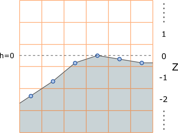
Fig. 26.2 Figure that illustrates the layout of the depth index in the terrain cell structure via cross-section view in the x/z plane. The orange
grid shows the cell boundraries in the terrain structure and the blue points shows the height field vertex height positions. The local
terrain center z position of the grid cell with depth index 0 is defined where the height of the coupled heightfield is zero. The lowest
allowable z index corresponds to the grid cell where the maximumDepth reaches.
3D grid data is usually accessed via the TerrainGridControl interface. Often one wants to extract the depth index for the terrain surface given a surface index:
/**
Find terrain surface depth index given the terrain index x,y coordinates.
\param terrainIndex - The specified 2D terrain surface index.
\return The terrain depth index (z) at the surface.
*/
int TerrainGridControl::findSurfaceIndex(const agx::Vec2i& terrainIndex) const;
26.2.2. Mass Data
Each grid cell contains information about how much solid terrain mass it contains. It is represented as cell occupancy.
Assuming nominal compaction (1.0), each cell can have an occupancy value that can range from 0.0 (empty) to 1.0 (full).
If the cell has a compaction value other than 1.0, the amount of solid occupancy that can be stored in a grid cell changes according to:
where \(0_{{max}_i}\) is the new maximum occupancy that can be stored in cell \(i\), \(0_{max}\) is the nominal maximum occupancy that can be stored in a cell (1.0) and \(c_i\) is the compaction in cell \(i\). This effectively means that more mass can be contained in dense packed soil and less in looser soil.
26.2.3. Accessing Grid Data
Grid data can be modified or inspected at the grid level through the agxTerrain::TerrainGridControl which can be accessed from the
Terrain object.
Terrain solid mass is modified in the occupancy format top-down on the terrain surface at a 2D index. Either
is it added via specifying the amount occupancy or by filling/removing up to a certain height or layer.
Note
The terrain does not support discontinuous terrain mass in the z-direction due to the nature of the surface heightfield. That is why mass can only be added/removed columnwise top-down on the terrain surface.
The following snippet shows some functions that enables the user to do this:
float addSolidOccupancyInColumn(const agx::Vec2i& terrainIndex, float occupancy, float compaction, bool shouldAvalanche = true);
float removeSolidOccupancyInColumn(const agx::Vec2i& terrainIndex, float occupancy, bool shouldAvalanche = true);
float addSolidOccupancyLayerInColum(const agx::Vec2i& terrainIndex, agx::Real layerHeight, float compaction, bool shouldAvalanche = true);
float addSolidOccupancyInColumnToHeight(const agx::Vec2i& terrainIndex, agx::Real height, float compaction, bool shouldAvalanche = true);
The following snippet shows how to add a layer of loose soil on top of the terrain surface via the agxTerrain::TerrainGridControl object:
auto gridControl     = terrain->getTerrainGridControl();
auto terrainMaterial = terrain->getTerrainMaterial()->getBulkProperties();

// Add a loose layer of 0.5 m on top of the terrain that has compaction according to the swell factor
agx::Real compaction = 1.0 / terrainMaterial->getSwellFactor();
agx::Real height     = 0.5; // height in meters
for ( int x = 0; x < terrain->getResolutionX(); x++ )
  for ( int y = 0; y < terrain->getResolutionY(); y++ )
  {
    gridControl->addSolidOccupancyLayerInColum( { x, y },
                                                height,
                                                compaction,
                                                true );
  }
26.2.4. Terrain Properties
The general properties of the terrain is stored in a agxTerrain::TerrainProperties object which can be accessed:
agxTerrain::TerrainProperties* properties = terrain->getTerrainProperties()
These properties contains useful options for locking terrain border height, enable/disable for various terrain functions. The following code shows how to set some of the available options:
properties->setEnableLockedBorders(true)
properties->setDeleteSoilParticlesOutsideBounds(true)
properties->setSoilMergeSpeedThreshold(0.06)
properties->setMaximumParticleActivationVolume(0.5)
properties->setPenetrationForceVelocityScaling(0.05)
26.3. Shovel
agxTerrain::Shovel objects are used in order to deform the terrain. A shovel is an object that can represent different types of
tools used in earthmoving operations, from an excavator bucket to a bulldozer blade. The shovel deforms the terrain during digging and
deformation operations via failure/active zones that converts terrain solid to dynamic mass. The shovel experiences
feedback forces from penetration resistance and soil aggregates that are generated from the masses in
the active zone. The shovel can also compress the soil when no excavation is in progress.
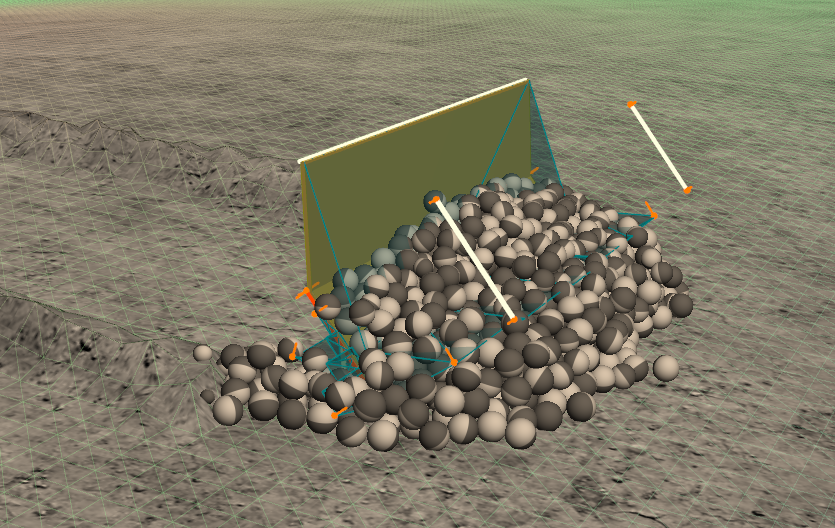
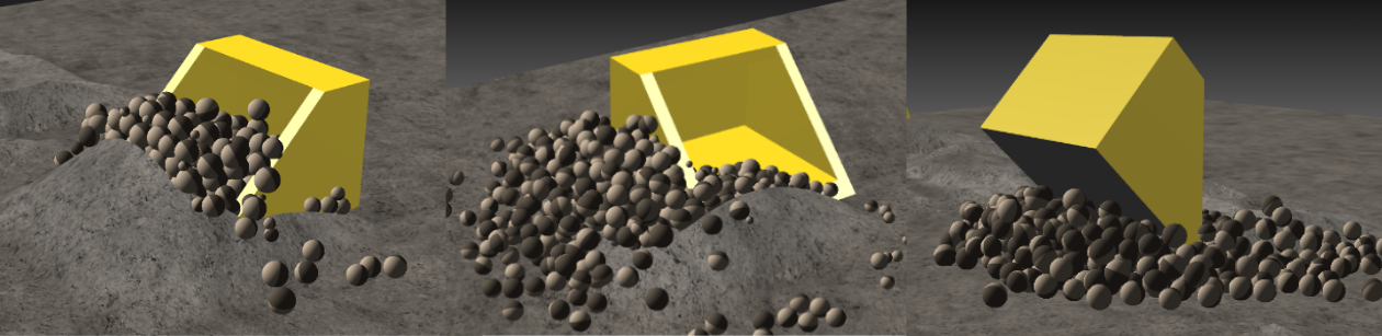
Fig. 26.3 Figure of a simple two-body agxTerrain::Shovel digging in a agxTerrain::Terrain object, converting solid mass to dynamic soil particle mass in the active zone ( light blue wedges in front, to the side and in the back of the shovel ) which is computed via soil failure mechanics. An aggregate body is generated from the dynamic mass inside the zone and exerts a resistance force against blade via constructed contact points ( orange ).
A shovel can deform the terrain via the following applications:
Digging |
This is done by driving the shovel in the cutting direction into the terrain, converting solid mass to dynamic mass. See figure 1 left. |
Push/Pull |
This is done via doing push/pull operations with the sides or backside of the shovel. See figure 2 middle. |
Grading |
This is moving the soil using the backside of the shovel. See figure 2 right. |
A shovel object is created by specifying a rigid body, one top edge, a bottom cutting edge and a cutting vector. The top and bottom edges
define the cross-sectional front area of the shovel geometry. The cutting vector is typically parallel to the shovel bottom plate, called separation plate,
that is initially used to penetrate the soil and is the basis for the penetration resistance. The shovel edges specified are used with the shovel body bounds to approximate excavation planes which form the basis for the digging operations.
There are 4 different excavation planes that are active on a shovel:
Primary |
This is the primary excavation mode of the shovel that is driven by the |
Deformer Back |
This is the deformer plane defined by the underside of the shovel. Used in grading and push operations. |
Deformer Left |
This is the deformer plane to the left side of the shovel. Used in grading and push operations. |
Deformer Right |
This is the deformer plane to the right side of the shovel. Used in grading and push operations. |
Each excavation plane is associated with a shovel cross-section plane that contains a top and a cutting edge. Only the primary excavation plane egdes are supplied by the user in the shovel constructor. The rest of the planes are automatically constructed via the geometry.
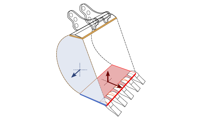
Fig. 26.4 Illustration of a digging tool is constructed with primary with a cutting edge (red line), separation plate ( driver of primary excavation/digging ) (red face), deformer edge (blue line), deformer face (blue face) and top edges (yellow line). The inner shape is indicated with the dashed lines. The penetration direction, separation normal and deformation normal vectors are indicated.
Shovel objects interact with the terrain by converting solid mass to dynamic mass via the active zones in both digging and deformation operations.
The active zone consists of soil wedges created that approximate the expected failure zone of the soil in the shovel <-> terrain intersection. The shape
of the failure zone soil wedge are calculated using soil mechanics theory based in the Fundamental Earth Moving Equation (FEE). The main parameters that
determine the shape and tilt of the soil wedges are the friction angle of the material and the cutting direction.
As the shovel moves it converts solid mass into dynamic mass, consisting and internal fluid and particle mass.
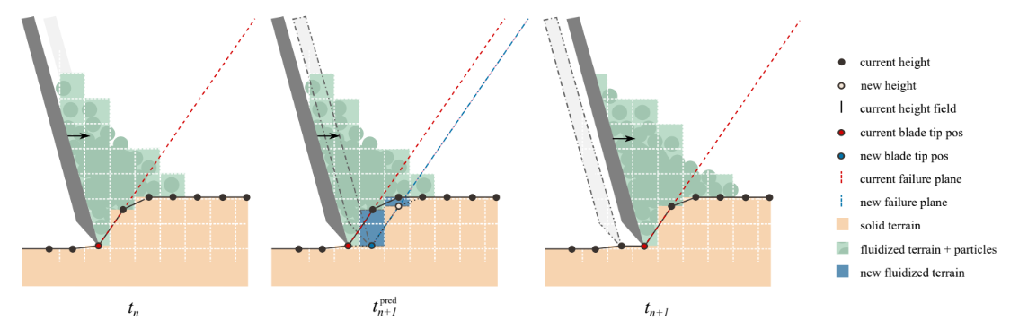
Fig. 26.5 Conceptual image of how the shovel converts solid terrain mass to dynamic mass via active zone intersection during a time step. The dynamic material inside the active zone define an aggregate body that the blade experience as a single rigid body through a reduced contact set. The aggregate is in contact with the shovel and also the terrain in the active zone intersection plane.
26.3.1. Shovel Setup
The top edge, cutting edge and cutting direction must be specified by the user in local body coordinates and should coincide with the geometry.
Both simple box geometries and more complex mesh shapes can be used. In the case of a more complex mesh, a convex hull will be created via the top and
cutting edge and the mesh shape in order to estimate the volume, the inner shape, between the active zone wedge and the confines of the shovel
body geometry.
Note
The top edge should ideally be placed at the upper confines of the cross-sectional digging area. The cutting edge should coincide with
the lowest edge on the shovel that is expected to remove soil. The cutting vector is typically parallel to the shovel bottom plate that is initially
used to penetrate the soil.
Note
The cutting direction should ideally be normalized with length 1.0. If this is not the case a warning will be given upon Shovel construction
(see constructor signature below) and the direction vector becomes re-normalized inside the object.
A shovel is created via the following constructor:
agxTerrain::ShovelRef shovel = agxTerrain::Shovel( agx::RigidBody* shovelBody,
                                                   const agx::Line& topEdge,
                                                   const agx::Line& cuttingEdge,
                                                   const agx::Vec3& cuttingVector );
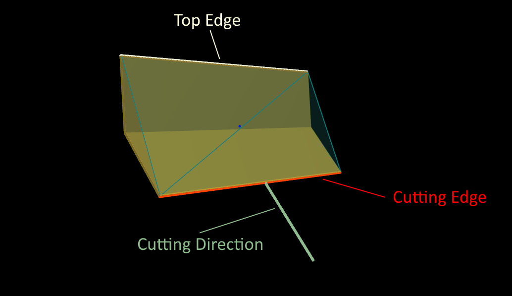
Fig. 26.6 Figure of the basic components needed in order to create a shovel. A top edge is placed on the upper confines of the expected digging area,
a cutting edge is placed on the lowest confines of the digging are and a cutting direction is placed along the expected cutting direction
of the shovel which typically is parallel to the bottom plate of the shovel.
Each excavation planes have individual settings which allows the user to control aspects of the digging depending on the
type of operation. The settings are store in a Shovel::ExcavationSettings object that can be extracted from the Shovel object
via the following function:
/**
Get a settings object for an ExcavationMode of the shovel. Excavation modes are as follows:
  PRIMARY - The primary mode of excavation, where the shovel digs along the cutting
            direction in the terrain horizontal plane.
  DEFORM_BACK  - The mode of excavation where the shovel is digging in the opposite
                  direction of the cutting direction in the terrain horizontal plane.
                  ( Example: Backside grading )
  DEFORM_LEFT  - The mode of excavation where the shovel is digging to the counter-clock wise
                  (Left) direction orthogonal to the cutting direction in the terrain horizontal plane.
                  ( Example: Side push/grading )
  DEFORM_RIGHT - The mode of excavation where the shovel is digging to the clock wise
                  (Right) direction orthogonal to the cutting direction in the terrain horizontal plane.
                  ( Example: Side push/grading )
\param mode - The specified excavation mode that the settings will apply to.
\param excavationSettings - The specified excavation settings that will apply to the excavation mode.
*/
ExcavationSettings& getExcavationSettings(ExcavationMode mode);
The user can use this object, for example, specify if individual excavation planes should be enabled or create dynamic soil. The following snippet shows how to disable the left and right planes and the dynamic soil creation for the back plane.
shovel->getExcavationSettings( agxTerrain::Shovel::ExcavationMode::DEFORM_LEFT )->setEnable( false )
shovel->getExcavationSettings( agxTerrain::Shovel::ExcavationMode::DEFORM_RIGHT )->setEnable( false )
shovel->getExcavationSettings( agxTerrain::Shovel::ExcavationMode::DEFORM_BACK )->setEnableCreateDynamicMass( false )
The following are some of the more useful generic settings for configuring the Shovel object:
void setNoMergeExtensionDistance(agx::Real extensionDistance)
This function expands the no merge zone around the shovel, where dynamic soil is not allowed to merge with the terrain, with the specified distance in every axis of the bounding box. The default value is 0.5 m.
void setVerticalBladeSoilMergeDistance(agx::Real verticalSoilBladeMergeDistance);
Specifies the distance where dynamic soil instantly merges up to the blade cutting edge along the gravity direction, if the specified distance intersects with the terrain surface.
Note
This is useful for bulldozing and grading operations where the leveling process requires continuously merging soil in the gap between the shovel cutting edge and the terrain surface.
void setEnableParticleFreeDeformers(bool enable);
This function enables/disables the deformers of the shovel to interact with the terrain without creating particles.
26.4. Excavation Forces
The force feedback on the shovel is created via the following phenomena:
Generated by digging and pushing soil in the forward digging direction. |
|
Force generated via penetration of the cutting plate in the cutting direction. |
|
Similar to the separation forces but generated during push/pull/grading operations. |
|
Generic Contact Forces |
These are the regular contact forces when no excavation mode is active. |
Note
It is recommended that the user always check their excavation forces during terrain setup. This is in order to properly asses the feasibility of the forces and phenomena that is generating feedback.
The force feedback that is generated from a terrain on a shovel can be extracted by the following methods:
bool Terrain::getPenetrationForce(const Shovel* shovel, agx::Vec3& force, agx::Vec3& torque) const;

agx::Vec3 Terrain::getSeparationContactForce( const Shovel* shovel ) const;

agx::Vec3 Terrain::getDeformationContactForce(const Shovel* shovel) const;

agx::Vec3 Terrain::getContactForce( const Shovel* shovel ) const;
26.4.1. Excavation Force Model
Force feedback in the separation and deformation mode is generated by creating contacts with aggregate rigid bodies bodies
created from dynamic and solid mass in the shovel active zones. Contacts are created both between the shovel and the aggregate
and the aggregate and terrain. The resulting forces depend on the contact materials properties which are derived from the
agxTerrain::TerrainMaterial bulk properties and also the contact material between the shovel and
the terrain that is used for the shovel-aggregate contacts.
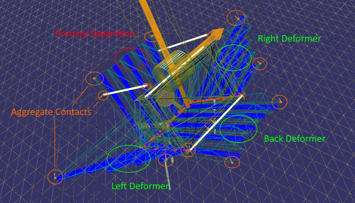
Fig. 26.7 Figure showing the aggregate formation during excavation. Primary separation resistance is denoted in red and the deformer zones are denoted in green. The resulting aggregate contacts for aggregate <-> terrain and aggregate <-> shovel are denoted in orange. The blue lines denote the direction of the soil wedges that are created in the terrain via calculation using the Fundamental Earth Moving model (FFE) and the material bulk properties. These soil wedge shapes are the basis for the failure zone that ultimately form the soil aggregates in the separation and deformer zones.
26.4.2. Calibration of Excavation Resistance
The following aspects determine the excavation force:
Contact properties between the shovel and the terrain aggregate and geometry. This is controlled by the contact material specified between the shovel geometries and the terrain.
Soil properties, such as soil density, stiffness and friction angle. This determines soil aggregate weight and also internal contact properties, i.e contacts between the aggregate and the terrain.
The following parameters determines the internal contact and shape properties of the soil aggregates. Most of them are found the in the bulk properties but some are also found in excavation contact properties.
|
Determines the stiffness in the contacts between the aggregate <-> terrain contacts. |
|
Affects the force feedback from the terrain via setting a cohesion value in the aggregate <-> terrain contacts. |
|
This affects the angle of the failure zones and also determines the friction coefficient in the aggregate <-> terrain contacts via \(\tan{ \psi }\). |
|
Affects the total mass of the soil aggregates formed the shovel active zone. |
|
Scales the bulk Young’s modulus applied in the shovel <-> aggregate contact in order to allow the user to fine-tune the excavation force. |
|
Scales the bulk Young’s modulus applied in the aggregate <-> terrain contact in order to allow the user to fine-tune the excavation force. |
26.4.2.1. Shovel - Terrain Contact Material
The contact material specified between the shovel and the terrain is the primary determinant of excavation resistance. The contact properties are used in the shovel-aggregate contact for all excavation modes. It is also used in regular geometry contacts between the shovel and the terrain when there is no active excavation mode.
agx::MaterialRef shovelMaterial = new agx::Material("Shovel");
simulation->add(shovelMaterial);
// ... set the shovel material on the shovel bodies

agx::MaterialRef terrainMaterial = terrain->getMaterial( agxTerrain::Terrain::MaterialType::TERRAIN )
agx::ContactMaterialRef shovelTerrainCM = new agx::ContactMaterial( shovelMaterial, terrainMaterial );
shovelTerrainCM->setFrictionCoefficient( 0.4 );
shovelTerrainCM->setYoungsModulus( 1e8 );
shovelTerrainCM->setRestitution( 0.0 );
shovelTerrainCM->setAdhesion( 0, 0 );
simulation->add( shovelTerrainCM );
26.4.2.2. Overriding Contact Material in Excavation Modes
The user can override the contact material between the shovel and the terrain for certain excavation modes. This can be desirable if different excavation modes should experience different resistance. This is done on a shovel-terrain basis and uses the folllowing function:
/**
Explicitly set contact material properties in a shovel-aggregate contact for a specific
excavation mode for a specific shovel-terrain pair. This overrides the shovel-terrain contact
material properties that are used in the default case.
\param shovel - The specified shovel.
\param contactMaterial - The contact material to be set in the aggregate contact.
\param excavationMode - The specified excavation mode that corresponds to the aggregate.
\note - this returns false if the shovel is not set to the terrain.
\return true if the contact material was successfully set, false otherwise.
*/
bool setShovelAggregateContactMaterial( const Shovel* shovel,
                                        agx::ContactMaterial* contactMaterial,
                                        Shovel::ExcavationMode mode = Shovel::ExcavationMode::PRIMARY );
The following example illustrates overriding the default contact material used in the back deformer with a custom contact material.
  terrainMaterial = terrain->getMaterial( agxTerrain::Terrain::MaterialType::TERRAIN )
  shovelTerrainContactMaterial = agx.ContactMaterial( shovelMaterial,
                                                      terrainMaterial )
  shovelTerrainContactMaterial->setYoungsModulus( 1e5 )
  shovelTerrainContactMaterial->setFrictionCoefficient( 0.2 )
  shovelTerrainContactMaterial->setRestitution( 0.0 )
  shovelTerrainContactMaterial->setAdhesion( 0.0, 0.0 )
  simulation->add( shovelTerrainContactMaterial )
  terrain.setShovelAggregateContactMaterial( shovel,
                                             shovelTerrainContactMaterial,
                                             Shovel::ExcavationMode::DEFORM_BACK )


.. note: In order to reset the contact material to the default shovel-terrain contact material, simply use the method above with nullptr
         as the contactMaterial argument.
26.4.3. Penetration Resistance Model
Pure penetration occur when a thin tool moves straight into the terrain, displacing only the soil necessary for fitting the tool. Buckets are often penetrated deep into the soil before separation (cutting) starts. The penetration resistance experienced by a tool consists of two main parts: from the teeth (or edge) and from the primary separating plate. The resistance from the separating plate contacting the soil is simply modeled by a frictional force proportional to the passive earth pressure in the soil. The pressure on the teeth during penetration can be modeled by using the cavity expansion model. The penetration force acts in the cutting direction of the Shovel.
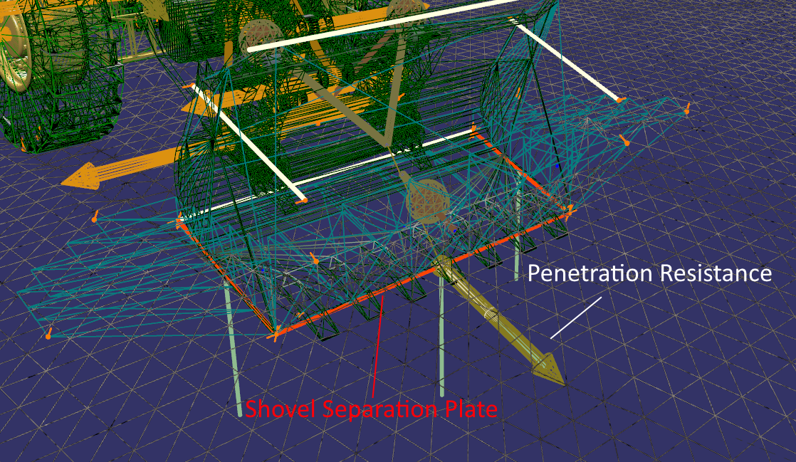
Fig. 26.8 Figure illustrating the shovel <-> terrain interaction during a wheel loader digging process. The penetration resistance works in the cutting direction parallel to the separation plate of the bucket and is expressed as a prismatic velocity constraint with force limits according to the penetration model theory.
26.4.3.1. Calibration of Penetration Force
The user can explicitly control the penetration force either by apply a scaling factor or a maximum cap on the penetration force:
/**
Set the linear scaling coefficient for the penetration force (Default: 1.0)
\param penetrationScaling - The coefficient for scaling the penetration force that the terrain will give on this shovel
*/
void agxTerrain::Shovel::setPenetrationForceScaling(agx::Real penetrationForceScaling);

/**
Set a maximum limit on penetration force (N) that the terrain will generate on this shovel. (Default: Infinity)
\param maxPenetrationForce - The maximum penetration force that the terrain will act on this shovel
*/
void agxTerrain::Shovel::setMaxPenetrationForce(agx::Real maxPenetrationForce);
26.5. Angle of Repose
agxTerrain can model soil repose effects when changes in the terrain surface causes the soil angle between two adjacent elements to exceed the specified angle of repose of the material. The base angle of repose of a material, in the bank state umodified by compaction, is given by adding the internal angle of friction and the delta repose angle:
Where \(\psi_{r}\) is the effective repose angle of the material, \(\psi\) is the internal friction angle and \(\delta \psi_{r}\) is the delta repose angle of the material.
Local soil compaction modifies the angle of repose for specified grid elements at a rate specified by the angleOfReposeCompactionRate.
26.6. Soil Compaction
Soil compaction determines how much soil mass that can exist inside a terrain 3D grid element. The default compaction value for a grid element is 1.0 which is defined as the bank state. As the compaction level changes, so does the local material properties in that grid element such as Young’s Modulus and angle of repose. Every material has a swell factor which determines the fractional increase in soil volume during excavation which also decreases the compaction.
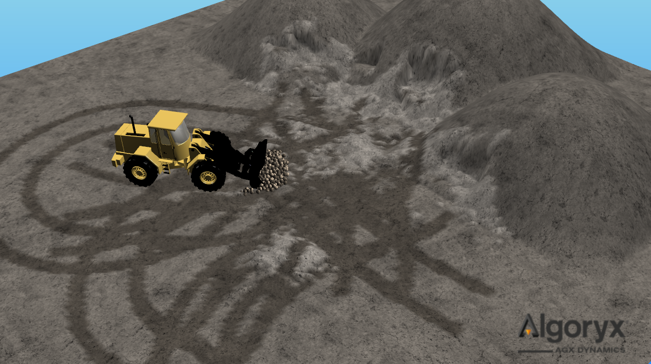
Fig. 26.9 Figure showing a wheel loader scene during excavation that illustrates terrain soils of different compaction levels through
lightness rendering. Dark surface patches in the soil shows wheel tracks from compressed soil with a compaction level higher
than the nominal compaction. The lighter areas show soils of looser compaction resulting from excavation or avalanching where
it grows in volume according to the swell factor of the material. Soil of loose compaction offers less resistance and is
easier to compress.
Default compaction for an initialized terrain is 1.0 in all terrain grid elements. Compaction can be set for all grid cells via the following function:
/**
Set a compaction for all current active solid grid elements in the Terrain object.
\note - the terrain grid elements all start with a the nominal compaction value of 1.0, of which all
user specified bulk parameters correspond to.
\param compaction - The compaction value to set to every voxel in the terrain (Default: 1.0)
\param replaceCompactedSoil - True if all voxels which already have a compaction value (compaction != 1.0)
                              should get overwritten.
*/
void setCompaction(agx::Real compaction, bool replaceCompactedSoil=true) const;
The TerrainGridControl class can be used to access and set the compaction value for single grid cells at the surface or at a 3D grid index.
float TerrainGridControl::getCompaction(const agx::Vec2i& terrainIndex, int z) const;
float TerrainGridControl::getSurfaceCompaction(const agx::Vec2i& terrainIndex) const;
void TerrainGridControl::setCompaction(const agx::Vec3i& terrainIndex, float compaction, bool compressOccupancy = false);
void TerrainGridControl::setSurfaceCompaction(const agx::Vec2i& terrainIndex, float compaction, bool compressOccupancy = false, bool compressToBottom = false);
Compaction can also be set from the surface to a specified depth:
void TerrainGridControl::setSurfaceCompactionToDepth(const agx::Vec2i& terrainIndex, float compaction, float depth);
The soil is normally compacted via contacts from external geometries that generates surface terrain contacts where the contact area is calculated from the voxels that the geometry is overlapping. A uniform surface stress in the voxel contact patch is estimated from the contact force and the estimated area. The active terrain contacts that generate soil pressure can be extracted from the terrain and it’s properties extracted:
auto terrainContacts = terrain->getTerrainContacts();
for( const auto& c : terrainContacts )
{
  auto geometry           = c.getGeometry();
  agx::Real surfaceStress = c.getSurfaceStress();
  agx::Real area          = c.getArea();
}
Pressure propagates down into the soil by apporximating the surface in each voxel as a uniform plate. The pressure thus decays according to the formula:
where \(\sigma^{v}_{z}(z)\) is the local stress in depth \(z\) from the surface, \(A_s\) is the plate area and \(\sigma_s\) is the uniform surface stress.
The soil is compacted in a grid cell if it exceeds the local preconsolidation stress from earlier compactions
or the starting preconsolidation stress. The level of compaction is determined by the specified compression index
and the preconsolidation stress in the Compaction Properties. The compression index is defined as a logarithmic
dependence between the change in compaction/void ratio from stress:
The new density in a grid cell is thus calculated via the following expression:
where the \({\phi}_0\) is the volume fraction of the material, \(\sigma_0\) the preconsolidation stress of the material, \(C_c\) the compression index of the material, \(\sigma\) the local stress and \(\rho_0\) the density if the material at compaction 1.0 (i.e the bank state).
This is then used to calculate the compaction level at grid cell \(i\):
One can apply a time relaxation to the rate of compaction changes in the terrain. It is governed by the following equation:
where \(\tau\) is the time relaxation constant and \(t_c\) is the contact duration time. The timefactor is multiplied with the estimated density changes and approaches 1.0 as the contact time increases.
The parameters for the soil compaction algorithms can be found and adjusted in the CompactionProperties object.
26.6.1. Material changes from compaction
Some material properties change locally from compaction level.
26.6.1.1. Young’s Modulus
The local Young’s Modulus in a grid element changes according to the following relation:
where \(E_0\) is the bulk elasticity in the bank state and \(k_e\) and \(n_e\) are hardening parameters that have default values of 1.0 and 0.5 respectively.
26.6.1.2. Swelling
When solid soil undergoes transformation to dynamic soil during excavation, the soil particle bulk volume expands according
to the specified Swell Factor of the material. When the dynamic soil is transformed back to solid during merge it will
have a compaction level according to:
where \(c_i\) is the local compaction at grid element i and \(S_f\) is the Swell Factor.
26.6.1.3. Angle of Repose
The local angle of repose changes with varying compaction levels by adjusting the allowed relative heights between two grid elements by using the following formulation:
where \(M\) is a constant, \(\psi_{r}\) is the effective repose angle of the material, \(L\) is the length of a grid cell, \(c_i\) is the local compaction level at cell i. This effectively means that compaction levels above 1.0 increases the angle of repose for the material.
26.7. Terrain Material Configuration
How the soil behaves during excavation is dependent on the terrain material parametrization, which is done in the following ways:
Specifying a
agxTerrain::TerrainMaterialfor the Terrain. This required the user to specify bulk, compaction and soil particle properties manually.Extracting the materials from the terrain in order to create external contact materials for objects in interacting with the terrain.
Use a pre-calibrated soil profile in
agxTerrain::Terrain::MaterialLibraryand set it on a terrain object. This will set the parameters according to the calibrated profile.Extract relevat
agx::Materialobjects from the terrain and configure contact materials between external objects and the terrain.
26.7.1. Terrain Material
agxTerrain::TerrainMaterial is used to describe the material properties of the soil in agxTerrain. The properties are grouped internally in objects
according to the phenomena they affect:
|
These properties govern general bulk behaviour such as soil density, failure zone shape and excavation forces. |
|
These properties govern behaviour of the soil compaction that happens. |
|
These properties govern the soil particle dynamics. Mostly contains parameters for the contact material in-between particles and particle <-> terrain contacts. |
26.7.2. Material Library
Instead of manually specifying material parameters the user can use an existing preset of material properties in the agxTerrain::TerrainMaterialLibrary.
This creates agxTerrain::TerrainMaterial that exemplifies typical soil profiles. Setting a material profile will modify the internal contact materials according
to it’s soil type. The available material presets are stored as external files in JSON format and are from parsed the default material library
folder in AGX Dynamics. Users can also create their own material presets files representing other soil types specific to their use cases. The
TerrainMaterialLibrary can be used to interface against arbitrary folders with .json files and TerrainMaterialReadWriter
can be used to read and write agxTerrain::TerrainMaterial to preset files.
26.7.2.1. Loading a TerrainMaterial Preset
This is done by using the following utility function on the agxTerrain::Terrain object:
bool agxTerrain::Terrain::loadLibraryMaterial( agx::String& filename );
The profiles that can be set correspond to the default set of .json files in the AGX Dynamics installation. The available default material presets can be extracted by using the following method:
agx::StringVector getAvailableLibraryMaterials() const;
The default set of presets are as follows:
gravel_1 |
Represents typical material properties for coarse gravel. |
sand_1 |
Represents typical material properties for fine sand. |
dirt_1 |
Represents typical material properties for cohesive dirt. |
Warning
Changing the bulk material properties or internal contact material parameters will invalidate the previous settings applied from the material library. The profile must be applied again in order to get the properties back.
26.7.2.2. TerrainMaterialLibrary
agxTerrain::TerrainMaterialLibrary is a utlilty class that helps handling folders of JSON files specifying agxTerrain::TerrainMaterial
presets. It parses a specified folder of files and stores verified material presets in tables according to material name.
This class is used by the agxTerrain::Terrain::loadLibraryMaterial when loading material presets. By default, this library folder
contains the default TerrainMaterial presets in AGX Dynamics. The user can specify their own folder with JSON files.
The following method loads a material profile according to material name in the specified library folder:
/**
Create a agxTerrain::TerrainMaterial object from one of the existing library
presets, derived from the .json files in the specified library folder. The default location
of the preset folder contains the default material preset of AGX Dynamics.
Note - Existing library materials can be extracted via the getAvailableLibraryMaterials() method:
\param materialName - the name of the material preset to load.
\param librayFolder - The path to the folder containing all the terrain material preset files.
\return a TerrainMaterial object created from the specified material preset or nullptr if the creation failed.
*/
static agxTerrain::TerrainMaterial* loadMaterialProfile( const agx::String& materialName,
                                                         const agx::String& librayFolder = DEFAULT_TERRAIN_MATERIAL_LIBRARY_FOLDER );
The following method prints all available valid material presets in the specified library folder:
/**
Get the available TerrainMaterial presets from the existing.json files in the specified
material library folder. The default location of the preset folder contains the default
material preset of AGX Dynamics.
\param librayFolder - The path to the folder containing all the terrain material preset files.
\return a vector containing the available TerrainMaterial presets from the existing
        .json files in the specified material library folder.
*/
static agx::StringVector getAvailableLibraryMaterials( const agx::String& librayFolder = DEFAULT_TERRAIN_MATERIAL_LIBRARY_FOLDER );
26.7.2.3. TerrainMaterialReadWriter
The agxTerrain::TerrainMaterialReadWriter class is used to store and read material profiles in .json format and
is used by the agxTerrain::TerrainMaterialLibrary. The following methods are used to read and store files:
/**
Read TerrainMateiral configuration from a file in JSON format into a TerrainMaterial object.
\param filename - the filename of the file containing the terrain material configuration in JSON format.
\param terrainMaterial - the TerrainMaterial object that will be initialized with the data from the JSON file.
\return true if the file was successfully read, false otherwise.
*/
static bool readFile( const agx::String& filename, TerrainMaterial* terrainMaterial );
/**
Write a TerrainMaterial configuration to a file in JSON format.
\param terrainMaterial - the TerrainMaterial object that will be written to the JSON file.
\param filename - the filename of the file where the the terrain material configuration will be written in JSON format.
\return true if the file was successfully written, false otherwise.
*/
static bool writeFile( const TerrainMaterial* terrainMaterial, const agx::String& filename );
26.7.2.4. TerrainMaterial .json files
The basic preset file structure is in JSON format that the reflects the underlying class layout
of the TerrainMaterial class. Below follows a sample file for the preset dirt_1 where
comments describing the parameter units have been added:
{
  "BulkProperties" : {
      "adhesionOverlapFactor" : 0.050,       // Dimensionless
      "cohesion" : 12000.0,                  // Pa
      "density" : 1300.0,                    // kg/m3
      "dilatancyAngle" : 0.2268928027592629, // radians
      "frictionAngle" : 0.7504915783575616,  // radians
      "maximumDensity" : 2000.0,             // kg/m3
      "poissonsRatio" : 0.150,               // Dimensionless
      "swellFactor" : 1.280,                 // Dimensionless
      "youngsModulus" : 5000000.0            // Pa
  },
  "CompactionProperties" : {
      "angleOfReposeCompactionRate" : 24.0,        // Dimensionless
      "bankStatePhi" : 0.6666666666666666,         // Dimensionless
      "compactionTimeRelaxationConstant" : 0.050,  // Dimensionless
      "compressionIndex" : 0.110,                  // Dimensionless
      "hardeningConstantKE" : 1.0,                 // Dimensionless
      "hardeningConstantNE" : 0.08333333333333333, // Dimensionless
      "preconsolidationStress" : 98000.0,          // Pa
      "stressCutOffFraction" : 0.010               // Dimensionless
  },
  "ExcavationContactProperties" : {
      "aggregateStiffnessMultiplier" : 0.050,       // Dimensionless
      "depthDecayFactor" : 2.0,                     // Dimensionless
      "depthIncreaseFactor" : 1.0,                  // Dimensionless
      "excavationStiffnessMultiplier" : 1.0,        // Dimensionless
      "maximumAggregateNormalForce" : "inf",        // N
      "maximumContactDepth" : 1.0                   // m
  },
  "ParticleProperties" : {
      "particleCohesion" : 200.0,                   // Pa
      "particleFriction" : 0.40,                    // Dimensionless
      "particleRestitution" : 0.0,                  // Dimensionless
      "particleRollingResistance" : 0.10,           // Dimensionless
      "particleTerrainCohesion" : 200.0,            // Pa
      "particleTerrainFriction" : 0.70,             // Dimensionless
      "particleTerrainRestitution" : 0.0,           // Dimensionless
      "particleTerrainRollingResistance" : 0.70,    // Dimensionless
      "particleTerrainYoungsModulus" : 100000000.0, // Pa
      "particleYoungsModulus" : 10000000.0          // Pa
  },
  "name" : "DIRT_1"
}
26.7.3. BulkProperties
The bulk properties govern the general behaviour of the terrain, such as failure zone shape, soil density and feedback forces. It contains of the following parameters:
|
The bulk stiffness of the material in Pa. This affects the stiffness in the internal aggregate<->terrain contacts. |
|
Describes the internal cohesion of the material in Newton. This affects the force feedback from the terrain. It also determines the cohesion in aggregate<->terrain contacts. |
|
Describes the internal friction angle of the material. This affects the angle of the failure zones and angle of repose in a 1-to 1 ratio for the avalanching algorithm. It also determines the friction coefficient in aggregate<->terrain contacts. |
|
Describes the density of the soil in kg/m3. This translates to the specific density of the solid soil and the bulk density of the dynamic soil (i.e soil particles). |
|
Describes the maximum density of the soil in kg/m3. This implicitly determines the maximum compaction of the material. |
|
Specifies the fractional increase in bulk volume that occurs when solid soil is converted to dynamic soil. |
|
Specifies the dilatancy angle of the mateiral. Used in Penetration resistance calculations. |
|
Specifies the Poisson’s ratio of the mateiral. Used in Penetration resistance calculations. |
|
Adhesion Overlap Factor is the fraction of the soil particle radius that is allowed to overlap. This is used to simulate adhesion. Default value is 0.05 |
|
The delta repose angle increases the base angle of repose of the material on top of the internal angle of friction. Default value is 0.0 |
Note
The Swell Factor is inversely correlated to the compaction level of the dynamic soil when it is merged back to the terrain.
The bulk properties can be accessed and modified via the TerrainMaterial object:
auto terrainMaterial = terrain->getTerrainMaterial()
auto bulkProperties = terrainMaterial->getBulkProperties()
bulkProperties->setDensity( 1.4e3 )
bulkProperties->setFrictionAngle( 23.0 * ( 180.0 / agx::PI ) )
bulkProperties->setSwellFactor( 1.05 )
bulkProperties->setAdhesionOverlapFactor( 0.07 )
26.7.4. Excavation Contact Properties
The excavation contact properties govern the some of the contact dynamics between the shovel, soil aggregates and the terrain during excavation and deformation. Bulk Material properties are used to set parameters such as stiffness, friction and cohesion in the terrain-aggregate and terrain-shovel contacts but the excavation properties allows to user to access and manipulate the underlying contact model. The contact model between the soil aggregate and terrain aims to model elasto-plastic behaviour with a maximum depth limit and decay factors. There is also parameters for controlling the stiffness of the shovel-aggregate contact interface.
|
This adjust the stiffness of the shovel-aggregate contacts by multiplying the Young’s Modulus of the material that is set to the contact. See aggregate<->terrain contacts. |
|
Specifies the rate of depth increase in the aggregate-terrain contact when excavating and deforming. |
|
Specifies the rate of depth decay in the aggregate-terrain during the separation stage of the excavation and deformation contact. |
|
Specifies the maximum depth of the aggregate-terrain contact. |
|
Sets the maximum normal force that can be applied in the aggregate-terrain contact. |
The excavation properties can be accessed and modified via the TerrainMaterial object:
auto terrainMaterial = terrain->getTerrainMaterial();
auto excavationProperties = terrainMaterial->getExcavationContactProperties();
excavationProperties->setExcavationStiffnessMultiplier(0.05);
26.7.5. Compaction Properties
The compaction properties govern how the soil compacts under pressure generated from terrain contacts. See the soil compaction section for model details.
|
Hardening constant that determines how Young’s Modulus changes with compaction. |
|
Hardening constant that determines how Young’s Modulus changes with compaction. |
|
The initial consolidation stress that the soil in the bank state ( compaction = 1.0 ). Only stresses above this may increase compaction levels. |
|
The time relaxation constant that limits the rate of density changes due to compaction. |
|
Determines the fraction of the surface stress that will determine when to stop propagating stress down into the soil. |
|
Determines how angle of repose should change with varying compaction. |
The compaction properties can be accessed and modified via the TerrainMaterial object:
auto terrainMaterial = terrain->getTerrainMaterial();
auto compactionProperties = terrainMaterial->getCompactionProperties();
compactionProperties->setCompressionIndex(0.05);
26.7.6. Particle Properties
The particle properties determines the properties for the 6-DOF particles representing dynamic soil and also the contact parameters in particle <-> particle contact and particle <-> terrain interactions. Data about soil particles can be accessed via the soil simulation interface.
|
Determines the specific particle density. This is implicitly set via the density parameter in bulk properties. |
|
Sets the Young’s Modulus (Pa) for the particle |
|
Sets the restitution of the particle <-> particle contacts. |
|
Sets the friction of the particle <-> particle contacts. |
|
Sets the rolling resistance of the particle <-> particle contacts. |
|
Sets the cohesion (Pa) of the particle <-> particle contacts. |
|
Sets the the Young’s Modulus (Pa) of the particle <-> terrain contacts. |
|
Sets the restitution of the particle <-> terrain contacts. |
|
Sets the friction of the particle <-> terrain contacts. |
|
Sets the rolling resistance of the particle <-> terrain contacts. |
|
Sets the cohesion (Pa) of the particle <-> terrain contacts. |
The particle properties can be extracted via the TerrainMaterial object:
auto terrainMaterial = terrain->getTerrainMaterial()
auto particleProperties = terrainMaterial->getParticleProperties()
particleProperties->setParticleRestitution(0.05)
26.8. Setting up Contact Materials
There are 4 types of interactions that the terrain can have:
|
This is the interaction between the shovel and the terrain that happens via aggregate formation during excavation and deformation. The contact parameters here are derived from the contact material specified between the shovel and the terrain. See calibration of excavation resistance. |
|
This is the interaction between the terrain and external objects such as wheels and tracks. |
|
The interaction between the dynamic soil and the external object, such as shovels and tracks. |
|
The interactions between the dynamic soil particles. |
|
The interactions between the dynamic soil particles and the terrain surface. |
An agxTerrain::Terrain holds internal agx::ContactMaterial objects for the contacts between the soil particles
and the terrain and also in between the particles. The parameters for these are largely set by the parameters in the
ParticleProperties object. Interactions between the Terrain and external objects can be setup by configuring
external contact materials with the internal terrain agx::Material objects.
An exsiting material can be set to an agxTerrain::Terrain instance:
agx::MaterialRef shovelMaterial = new agx::Material("TerrainMaterial");
simulation->add(shovelMaterial);
terrain->setMaterial( shovelMaterial )
This replaces and reconfigures the internal agx::Materials and agx::ContactMaterial objects. These internal terrain materials
can be extracted by the user and be used in conjunction with other materials to create contact materials with external objects and interacting shovels.
agx::Material* getMaterial(agxTerrain::Terrain::MaterialType type) const;
The internal terrain materials are the following:
MaterialType::TERRAIN |
This is the material set on the terrain surface. This material can be extracted and used to construct contact material parameters between the terrain ground and vehicle. |
MaterialType::PARTICLE |
The internal material for the dynamic soil particles in the terrain internal simulation. This can be extracted to construct contact material between interacting objects and the terrain. |
The internal contact materials can be accessed via the following function:
agx::ContactMaterial* getContactMaterial(agxTerrain::Terrain::MaterialType type1, agxTerrain::Terrain::MaterialType type2);
Internal terrain agx::ContactMaterial exists between the following internal materials:
MaterialType::TERRAIN - MaterialType::PARTICLE |
This contact material determines how the dynamic soil particles interact with the terrain surface. |
MaterialType::PARTICLE - MaterialType::PARTICLE |
This contact material determines how the dynamic soil particles interact amongst each other. It also determines the contact parameters between the shovel and the active zone aggregate which affects the blade resistance force. |
These contact materials are calibrated via the agxTerrain::TerrainMaterial::ParticleProperties instance when it’s added to a terrain object. They can also be calibrated by applying a soil profile in agxTerrain::Terrain::MaterialLibrary.
The following example illustrates a typical setup for calibrating the different interactions than can exist in a terrain context:
//
// Init materials
//
agx::MaterialRef shovelMaterial = new agx::Material("Shovel");
simulation->add(shovelMaterial);
agx::MaterialRef vehicleMaterial = new agx::Material("vehicle");
simulation->add(vehicleMaterial);
agx::MaterialRef objectMaterial = new agx::Material("externalObjectMaterial");
simulation->add(objectMaterial);
agx::MaterialRef terrainMaterial = terrain->getMaterial(agxTerrain::Terrain::MaterialType::TERRAIN);
agx::MaterialRef particleMaterial = terrain->getMaterial(agxTerrain::Terrain::MaterialType::PARTICLE);

//
// Create a contact material between the terrain and the shovel. This serves as a basis for the excavation resistance
//
agx::ContactMaterialRef shovelTerrainCM = new agx::ContactMaterial(shovelMaterial, terrainMaterial);
shovelTerrainCM->setFrictionCoefficient(0.6);
shovelTerrainCM->setYoungsModulus(2e10);
shovelTerrainCM->setRestitution(0.0);
shovelTerrainCM->setRollingResistanceCoefficient(0.25);
simulation->add(shovelTerrainCM);

//
// Create a shovel material and extract the particle material from the terrain object in order to create a contact material between the particles and the shovel.
//
agx::ContactMaterialRef shovelParticleCM = new agx::ContactMaterial(shovelMaterial, particleMaterial);
shovelParticleCM->setFrictionCoefficient(0.4);
shovelParticleCM->setYoungsModulus(2e07);
shovelParticleCM->setRestitution(0.05);
shovelParticleCM->setRollingResistanceCoefficient(0.15);
simulation->add(shovelParticleCM);

//
// We also need to specify the contact material between other objects, such as vehicles, with the terrain.
// This must be done manually via extracting the internal terrain materials and constructing the contact materials explicitly.
//
agx::ContactMaterialRef groundVehicleCM = simulation->getMaterialManager()->getOrCreateContactMaterial(terrainMaterial, vehicleMaterial);
groundVehicleCM->setFrictionCoefficient(0.4);
groundVehicleCM->setYoungsModulus(2E7);
groundVehicleCM->setRestitution(0.05);
simulation->add(groundVehicleCM);

//
// Contact parameters can be specified between external objects added to terrain and the internal soil particles
// by extracting the particle material from the terrain and create a contact material with the object material.
//
agx::ContactMaterialRef objectParticleCM = simulation->getMaterialManager()->getOrCreateContactMaterial(objectMaterial, particleMaterial);
objectParticleCM->setFrictionCoefficient(0.1);
objectParticleCM->setYoungsModulus(2E7);
objectParticleCM->setRestitution(0.2);
objectParticleCM->setRollingResistanceCoefficient(0.1);
simulation->add(objectParticleCM);
26.9. Dynamic Soil
Dynamic mass is created in the active zone intersection between the Shovel and the Terrain. It consists of both fluid mass and soil particles.
Soil particles are expressed in the form of 6-degrees of freedom (6-DOF) soil particles with hertzian contact dynamics, Coulomb friction and rolling resistance. The user can access and create soil particles via the soil simulation interface. The soil particles created from the shovel active zone intersection is simulated in the main simulation and can interact with other objects. By default, only the particles see the shovels as kinematic objects. This means that the particles themselves do not give force feedback to the shovels. The mass in the active zone, from both dynamic and solid mass, is used in the construction of the active zone aggregate that generates force feedback on the shovel through created contacts.
Note
The number of active soil particles depends on the amount of grid points touched by the dig volume which is a function of both blade size, dig depth, terrain resolution and dig length. A larger volume of influence means increased numbers of touched grid points and created particles which leads to an increase in computational time.
Soil particles are created when the active zone of the shovel touches new grid points. Fluid mass is generated if the shovel continues to remove mass from the same grid point and is then spread onto existing particles in the area, increasing their size. The fluid mass movement is integrated using a velocity field in the terrain grid generated from the shovels and the soil particles. If there are no particles that the fluid can merge to, it will merge back to the terrain.
Particles are also resized locally to cluster around a nominal radius. This is calculated from the resulting element size upon
construction of the terrain object. It is also modified by the material swell factor and estimated packing ratio of the particles so that
the total bulk volume of the particles created should correspond to the volume excavated, modified by the expected volume swelling. This radius can
be extracted by using the following function:
agx::Real getParticleNominalRadius()
The radius that the particles cluster around can be altered using the soil particle scaling factor. What this does is that it alters the
average radius of the soil particles, this can be used either to reduce the number of particles in the simulation to gain a potentially significant
performance increase, or by increasing the number of soil particles to increase fidelity or better dynamic soil visuals. This scaling factor can be
set and extracted using the following functions respectively:
void getProperties()->setSoilParticleSizeScaling( 1.5 )
agx::Real getProperties()->getSoilParticleSizeScaling()
The contact network between the soil particles is solved using an iterative Parallel-Projected-Gauss-Seidel Solver (PPGS) together with the rest
of the system. It is enabled in the simulation as soon as a terrain instance is added. The user can also set the fidelity of the solver by adjusting
the setNumPPGSRestingIterations which sets the number of iterations used in the PPGS solver. Increasing the iteration number typically results
in the better solution and may be necessary when the particle counts increases in the simulation in order to get correct bulk behavior with stable
particle piles that merge properly with the terrain. The default number is 25 iterations:
simulation->getSolver()->setNumPPGSRestingIterations( 25 );
simulation->getSolver()->setUseParallelPgs( false );
Warning
The PPGS solver currently disables island partitioning which means that performance will be lost if the scene contains multiple self-contained systems.
26.9.1. SoilSimulationInterface
Users can extract the agxTerrain::SoilSimulationInterface to access and create soil particle data
in the terrain. The currently active dynamic soil particles in a simulation can be accessed via the
following function:
auto soilSimulationInterface = terrain->getSoilSimulationInterface();
agx::Real totalMass{ 0.0 };
agx::Real averageRadius{ 0.0 };
auto soilParticles = soilSimulationInterface->getSoilParticles();
for ( auto& particle : soilParticles )
{
  totalMass += particle->getMass();
  averageRadius += particle->getRadius();
  agx::Vec3 position = particle->getPosition();
  agx::Vec3 velocity = particle->getVelocity();
}
averageRadius /= soilParticles.size();
Note
Do note that changing either mass, material or radius will change the mass of the particle and thus violate mass conservation.
Warning
It is not recommended to change particle properties such as mass and material as those are derived from the Terrain instance.
Individual soil particles can be created and removed manually:
auto soilSimulationInterface = terrain->getSoilSimulationInterface();
agx::Real radius = terrain->getParticleNominalRadius();
agx::Vec3 position{ 0.0, 0.0, 1.0 };
agx::Vec3 velocity{ 0.0, 0.0, 0.0 };
auto soilParticle = soilSimulationInterface->createSoilParticle(radius, position, velocity);
soilParticle->setPosition( ... );
soilParticle->setVelocity( ... );
...
soilSimulationInterface->removeSoilParticle( soilParticle );
Before doing any operations on the particles in the terrain, it can be useful to check if the particle is valid or not already removed:
auto soilParticles = soilSimulationInterface->getSoilParticles();
for ( auto& particle : soilParticles )
{
  if ( soilSimulationInterface.isValid( p )
  {
    ...
  }
}
Soil particle collisions can be controlled via the collision group system in agxCollide::Space and
added to the created soil particles via the soil interface:
// Create a collision group and add it to all particles
agx::Name collisionGroup { "myCollisionGroup" };
soilSimulationInterface->addCollisionGroup( collisionGroup );

/**
Disable collisions between the objects that have the specified group. This will prevent particles
from colliding with eachother.
*/
simulation->getSpace()->setEnablePair( collisionGroup, collisionGroup, false );
The current active bulk volume of soil particles can be extracted by using the following function:
/**
\return soil particle bulk volume (m3) active in the simulation.
\note - the bulk volume is the specific volume of all particles divided with the
        estimated particle packing fraction (0.67)
*/
agx::Real calculateSoilParticleBulkVolume() const;
The internal GranularBodySystem used for simulating the soil particles can be extracted and used with other objects, such as a
agx::ParticleEmittter to create masses of soil particles.
agx::Physics::GranularBodySystem* getGranularBodySystem() const;
Warning
When using an emitter with the GranularBodySystem, the emitter particle material should be the same as the particle material of the terrain that the emitted particles should belong to! The particle material is used by different terrains in the simulation to determine which particle belongs to which terrain instance.
26.10. Performance notes
The performance of agxTerrain depends on the number of dynamic soil particles in the simulation. The number of active soil particles depends on the amount of grid points touched by the dig volume, which in turn is a function of both blade size, dig depth, terrain resolution and dig length. A larger volume of influence means increased numbers of grid points and more particles, and thus an increase in computational time.
The number of solver iterations set via setSolverIterations via SoilSimulationInterface also determines the overall performance. Increasing the
solver iterations is needed when particle count increases in order to get stable soil piles. A low iterations count relative to the amount of particles
will results in an error that introduces numerical vibrational noise in the contact forces, causing the particle piles to “melt”. A typical cue of when
to increase solver iterations is when the particles are unable to merge with the terrain due to this numerical noise.
Do note that the material parametrization of the terrain, with the exception of terrain resolutions, does not overtly affect the performance. This means that soil behavior should be achieved without compromising performance.
26.11. Terrain Paging
If a large area with dynamic terrain is needed, the memory requirements for the terrain can become a problem. To overcome this the terrain module has support for paged terrain.
This is achieved via the agxTerrain::TerrainPager class. It has a virtual 2D grid
with square tiles in which it can load in agxTerrain::Terrain instances as needed.
The Terrain instances are unloaded again when they are not needed any longer.
/**
 Constructor. Specifies tile information and the 2D-plane used for dynamic terrain tiles.

 The TerrainPager do not mirror all the different parameters a terrain exposes,
 instead a template terrain is used for settings.

 To support excavation, the terrain tiles have an optional margin. This margin can
 be set so that the excavation is performed within one tile and correct soil wedges
 are formed.

 Example: tileResolution = 301, tileOverlap 10, tileElementSize = 0.25, ....

          Each tile then becomes (301-1)*0.25 = 75m x 75m
          The overlap on each side will be 10*0.25 = 2.5m

 \param tileResolution    Specifies the number of height values for each dimension for (tile+margin).
 \param tileOverlap       Specifies the number of height values that should overlap between two tiles.
 \param tileElementSize   Size in meters for one element. Same as distance between two height values.
 \param maximumDepth      How deep in meters the terrain can be excavated
 \param referencePoint    A world reference point for where the terrain is located
 \param referenceRotation A rotation that will transform the Z-axis to the up direction at the referencePoint
 \param templateTerrain   A template terrain whose settings will be used for the terrain tiles.
 */

 TerrainPager(size_t tileResolution, size_t tileOverlap, agx::Real tileElementSize, agx::Real maximumDepth,
              agx::Vec3 refPoint, agx::Quat refRotation,
              agxTerrain::Terrain* templateTerrain );
Note
It is important that the edges of two adjacent tiles match. To handle this and support excavation, adjacent tiles can have an overlap. When excavation is performed, the soil wedges are kept within a tile and to have non-truncated soil wedges. The overlap should be larger than both the length of the cutting edge interacting with the terrain aswell as twice the expected maximum length of a soil-wedge (which depends on how deep excavation in the terrain will be performed).
Warning
Adding a Terrain instance to a Simulation will also set some Solver parameters that the terrain needs and cause the Simulation update task to be rebuilt. It is not supported to rebuild the update task when it is executing, that is, during Simulation::stepForward. It can cause Simulation::stepForward to not return.
The TerrainPager must be able to add and remove terrains during stepFoward. Hence, Simulation::add( TerrainPager) prepares the Simulation by setting the same solver parameters that Simulation::add( Terrain ) would do, preventing a later task rebuild.
After a TerrainPager has been added to a Simulation, it is not supported to change any of the following solver parameters: - setUseParallelPgs - setUse32bitGranularBodySolver - setUseGranularWarmStarting Also, adding a TerrainPager to the Simulation will change the BroadPhase Algorithm used by Space to HIERARCHICAL_GRID. It is not supported to change it to SWEEP_AND_PRUNE.
26.11.1. Tracking bodies / shovels
To know which tiles that should have Terrain instances, bodies and shovels can be added to
the agxTerrain::TerrainPager for tracking.
Each tracked item have two radiuses associated with them:
The required radius: All tiles within this radius must be in the Simulation for
agxSDK::Simulation::stepForwardto be able to proceed. Can causestepForwardto wait while the tile processing occurs in the background.The preload radius: Tiles within this radius will be preloaded in the background and inserted into the Simulation when ready.
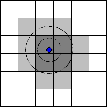
Fig. 26.10 Figure that shows a tracked item in blue, required tiles in dark gray and tiles within the preload radius in light gray. Normally the tiles are much larger than in this example image and fewer tiles are active.
The value for the required radius should be selected so that all geometries attached to the body that may interact with the terrain are enclosed within the radius. The value for the preload radius should be chosen so that tiles may be loaded into memory well before they will be needed in the simulation to avoid hickups. This means the higher the expected maximum velocity the higher the preload radius relative to the required radius.
/**
Adds a RigidBody to the terrain pager. The pager will make sure that terrain tiles
within the required radius are present in the Simulation before stepping and tiles
within the preload radius will be loaded and inserted when available.
*/
bool add( agx::RigidBody* body, agx::Real requiredTileRadius, agx::Real preloadTileRadius );


/**
Remove body so that the terrain pager no longer uses the body when determining
which terrain tiles that are needed.
*/
bool remove( agx::RigidBody* body );
26.11.2. TerrainDataSource
The TerrainPager must also have a TerrainDataSource from which it can request
height data for the needed tiles. The first time a tile is needed, heights are requested.
If the tile is paged out then the height values are stored to disk. If it is needed again
the possibly modified values are read from file and not requested from the data source.
There is one class that implements the TerrainDataSource interface:
agxTerrain::TerrainRasterizer. The TerrainRasterizer should be given source
geometry (e.g. large heightfield(s)) which it will then sample with raycasting to
get height values at the needed positions.
26.11.3. Paged Terrain settings
The TerrainPager do not expose the material settings for the terrain tiles. Instead, one of the arguments to the TerrainPager constructor is a template terrain. Each time a terrain tile is inserted into the simulation, the template settings are applied to the new tile.
/**
Fetches the template terrain.
The settings for the template terrain are used on new terrain tiles
when they are inserted into the simulation.

\see applyChangesToTemplateTerrain
*/
agxTerrain::Terrain* getTemplateTerrain();

/**
Signals to the TerrainPager that the template terrain has been updated
and that any changes to the template terrain should be applied to the
active terrain tiles in the pager.
*/
void applyChangesToTemplateTerrain();
Each time a new Terrain instance is inserted into the Simulation, the TerrainPager
triggers an event, tileLoadEvent, and in the same way when removing a Terrain
tileUnloadEvent is triggered. With these events it it also possible to customize
tiles settings per tile.
Compaction data for paged out tiles is not stored by default. If this is needed the method
TerrainPager::setShouldStoreCompaction( bool, size_t ) can control this and specify
how many voxels below the surface that should be stored.
Note
The amount of stored data per paged tile will increase greatly if maximumCompactionDepth is set too high.
26.11.4. Serialization
The terrain pager has two ways of serialization. There is a full state serialization using InputArchive and OutputArchive and there is a serialization of modified terrain height data.
The full state serialization use the functions
void TerrainPager::store(agxStream::OutputArchive& out) const and
void TerrainPager::restore(agxStream::InputArchive& in).
Part of the state held by the terrain pager can be paged out to disk (see
TerrainPager::setFileCacheDirectory). The files in that directory are needed along with
the serialized archive. If needed, the paged out data can be embedded in the archive. This
is controlled via TerrainPager::setEmbedCacheFilesInArchive( bool ).
Furthermore, compaction data is not stored by default. If this is needed the method
TerrainPager::setShouldStoreCompaction( bool, size_t ) can control this and specify
how many voxels below the surface that should be stored.
Note
The amount of stored data per paged tile will increase greatly if maximumCompactionDepth is set too high.
The serialization for the changed heights uses the methods
void TerrainPager::store( agxTerrain::TileModificationVector& storeData );
void TerrainPager::restore( const agxTerrain::TileModificationVector& restoreData );
this is described in more detail below.
26.11.5. Store / restore of terrain height data
There are custom store/restore functions which can be used for serialization of paged terrains heights if needed.
If TerrainPager::setShouldStoreDeltas is enabled, then terrain pager will start collecting height
changes internally. Unless these values are fetched periodically, the internal structure
will keep growing. These delta changes can be fetched via
void TerrainPager::store( agxTerrain::TileModificationVector& storeData );.
The output is written to storeData and will contain the changes since last time the
function was called. After store has been called, the TerrainPager will clear its
internal buffer with changes.
To restore the system, void TerrainPager::restore( const agxTerrain::TileModificationVector& restoreData ); should be used.
The restoreData should be the aggregated state from all the store deltas.
This will give the terrain pager a set of changes which should be applied to a tile after
the height data has been requested from the terrain data source.
26.11.6. Terrain paging tutorials
A full example of how the TerrainPager and TerrainRasterizer can be used
along with dynamic loading/unloading of Terrain tiles can be seen in
data/python/agxTerrain/basic_paging_example.agxPy.
There is also an example which uses a kinematic body to
control which tiles that are preloaded and performs
efficient raycast measurements of the terrain height
data/python/agxTerrain/paging_depth_measurements.agxPy.
There is also a tutorial showing bulldozing with a terrain pager
data/python/agxTerrain/tutorials/agxTerrain/tutorial_bulldozing_terrain_paging.agxPy.