25. agxModel
agxModel is a library consisting of high level primitives which implement various simulation objects: trees, beams, terrain etc. They are built upon the basic construction elements found in the agxPhysics library: constraints, geometries, bodies and event listeners.
25.1. Terrain
Note
agxModel::Terrain is now deprecated. See agxTerrain
The agxModel::Terrain implementation is a high level API that can simulate the behavior of deformable ground. The implementation covers four different types of interaction with the ground.
The default behavior when a rigid body collides with the agxModel::Terrain is compression of the ground.
A geometry could have a property telling the terrain that it is a “deformer”, which will make the ground volume conserving, and push the ground sideways.
A geometry could also have the property of being a “shovel”, which allows to convert volume from the terrain to particles.
A geometry could also be both a “deformer” and a “shovel” which improves the digging experience.
25.1.1. Physical model
The height field must have symmetric scale. I.e. the distance between vertices in x-direction must be the same as in y-direction. An agx::LOGGER_WARNING will tell you if you have a bad configured height field scale.
The implementation is done so that it is only valid to have the height field z axis in the negative gravitational direction.
The terrain can be created using one height field shape, or one geometry that has only one shape. A height field, with no transform relative to the geometry.
agxModel::Terrain( agxCollide::HeightField* heightField );
agxModel::Terrain( agxCollide::Geometry* terrainGeometry );
25.1.1.1. Colliding
An agxModel::Terrain contains one geometry with one shape, an agxCollide::HeightField. The user may set a material map to each vertex of the terrain using a PNG picture:
agxModel::Terrain->getDataInterface()->setMaterialMapping(const std::string& filePath)
The file will contain indices to materials that are supposed to be active at certain material indices. User must connect materials to material indices:
agxModel::Terrain->getDataInterface()->add(agx::Material* material, size_t materialIndex)
This call to add could also set three other Terrain specific material properties, particleAdhesion, deformability and angleOfRepose (these are zero by default and will be explained later).
agxModel::Terrain->getDataInterface()->add( const agx::Material* material, const size_t materialIndex, const agx::Real particleAdhesion = agx::Real(0), const agx::Real deformability = agx::Real(0), agx::Real angleOfRepose = agx::Real(0) );
25.1.1.2. Digging
To be able to dig into the terrain some geometry must act as a shovel (or bucket). When a geometry with the two properties “ShovelUpProperty” and “ShovelForwardProperty” collides with the terrain, it will be considered being a shovel. If there is any volume from the terrain shape above (in height field coordinates) that volume will be removed from the height field and converted into particles.
The length of the shovel forward property will define the distance from the shovel geometry shape center to the tip of the shovel. The length of the shovel up property will define the thickness of the shovel when trying to cut through the ground. It should be orthogonal to the shovel forward direction, and point “up in the air” when the shovel is resting on the ground.
25.1.2. Configuration
There are several variables exposed for the configuration of the Terrain interaction. First, the general variables will be explained that will be used when any geometry is interacting with the terrain. Then the shovel specific variables are explained, and at last the variables that control the dynamic height field behavior.
25.1.2.1. Compression: Deformability
For a material which is added to a material index (in the material index map), the parameter deformability can be set. The deformability specifies how fast the ground gets harder when being compressed. For each delta length, dl, the ground is compressed, it will become exponentially harder (increased Young’s modulus) according to the formula:
youngsModulusMultiplier = (1/2)* 2 ^[ (deformability + 1 )*compression + 1 ]
The Young’s modulus for the local contact point will be multiplied with the youngsModulusMultiplier. The ground can’t become harder if the deformability is zero. And it will become harder exponentially faster with increased deformability.
25.1.2.2. Compression: Max compression multiplier
The ground will become harder and harder the more it gets compressed (unless the deformability is zero). The max compression multiplier specifies the upper limit for the compression multiplier. This scalar value should be a multiple of 2, since the log2 of the multiplier has to be calculated.
agxModel::Terrain->getDataInterface()->setMaxCompressionMultiplier(Real multiplier)
25.1.2.3. Compression: Depth for max compression
The deeper you dig, the more compressed the ground is, and the compression at a vertex will increase not only by compression, but also by removing volume (shovel or deformer can do that). So when digging into the ground, the ground will become harder and harder until you have reached the depth of max compression. At this depth and deeper the ground will be as hard as the max compression multiplier (and the young’s modulus of the contact) allows to.
agxModel::Terrain->getDataInterface()->setDepthForMaxCompression(Real depth)
25.1.2.4. Compression: Max Young’s change per time step
When objects are moving at a high velocity (in relation to the time step) the contact depths could be large, which could result in large deformations. The max young’s change per time step parameter could be set to control how compressed (and therefore how much harder) the ground can become during one time step.
agxModel::Terrain->getDataInterface()->setMaxYoungsChangePerTimestep( Real maxMultiplierChange)
25.1.2.5. Compression: Lock boarders
The terrain can have fixed height at the boarders. It is useful if the terrain is for example a pile of dirt on the flatbed of a truck.
agxModel::Terrain->setEnableLockedBorders( bool enabled)
25.1.2.6. Digging: Overall
The terrain will create particles when digging. The materials for the particles are set up by the terrain. Also, the contact materials between particles and between particles and explicitly specified external materials.
A shovel does not have to be a “deformer”, but it is recommended.
25.1.2.7. Digging: Particle creation
The particles will be created in a FCC pattern. The particles will overlap with (some of) their neighbors with exactly:
adhesiveOverlap = (radius*sqrt(2)-radius).
The radius of the particles should be no more than the scale of the height field. Otherwise it is very hard to create them without overlapping the height field too much.
25.1.2.8. Digging: Particle radius
Set the particle radius to the particle attributes.
agxModel::Terrain.getParticleAttributes()->setParticleRadius( Real radius )
The maximum accepted particle radius can be found from:
agx::Real agxModel::Terrain->getMaximumParticleRadius();
25.1.2.9. Digging: Particle adhesion
The particles can act as a lump of dirt or as granular material. The particles should be constrained somehow to simulate a lump. This is done by setting an adhesive force (using the defined adhesive overlap, (see Digging: Particle creation) between particles. It is done in the call where you map a material to a material index. That material will then have the specified adhesive force between particles when the region of the height field with that specific material is converted to particles.
25.1.2.10. Digging: External material
The interaction between particles and other materials will become very soft (as soft as the ground material is). Between the shovel and the particles, it is important that the contacts are quite hard, otherwise they will easily fall through the shovel. Terrain controls the contact material between particles and materials added to the terrain as external materials. The Youngs modulus of these contacts will be the largest Youngs Modulus value of the external material and the material of the terrain where the particle is created.
agxModel::Terrain->getDataInterface()->addExternalMaterial( agx::Material* material );
25.1.2.11. Digging: Particle Young’s multiplier
The stiffness of the contacts between particles could be scaled with the particle Young’s multiplier. If this multiplier is 1, the particles will have the same Young’s modulus as the material of the terrain where the particle is created (which could be very soft).
agxModel::Terrain.getParticleAttributes()->setParticleYoungsModulusMultiplier(Real multiplier)
25.1.2.12. Digging: Shovel min angle to horizontal plane
When the shovel cuts through the ground, particles can be created. The terrain logic only allows particles to be created when the shovel normal vector has a component in the negative gravitational direction (the shovel is NOT upside down). When the shovel is not upside down but very close to point (with the shovel forward vector) straight down into the terrain, the volume where particles can be created is just a crack in the ground. It could be (depending on the radius of the particles) that no particle fit in that crack and therefore impossible create particles at valid positions. Buy setting the shovel minimum angle to the horizontal plane for particle creation, the particles are not created until the angle between the shovel and the gravitational direction is big enough.
25.1.2.13. Digging: Shovel ground cutting force
If the shovel is both a deformer and a shovel and the interaction when the shovel is deforming and pushing soil is satisfactory, but it is too easy to dig, a constant friction force in the shovel forward direction can be added. This can also be changed in runtime, to simulate for example a full shovel/bucket that can’t dig as easily as when it is not full.
agxModel::Terrain->getDataInterface()->setShovelGroundCuttingForce( Real force )
When the shovel is not a deformer, this value is used as a friction coefficient scale, not a constant force limit.
25.1.2.14. Digging: Particle friction solve type
The contacts between particles is default solved iteratively which could reveal a soft behavior, compared to solving the contacts with the direct solver. By setting the particle solve type to agx::FrictionModel::DIRECT the particles will behave stiffer when they are compressed. However, using a DIRECT solve type will have a negative impact on performance.
agxModel::Terrain->getDataInterface()->setParticleFrictionSolveType( agx::FrictionModel::DIRECT );
To keep reasonable computational speed, we must make sure that the direct solver does not end up in any LCP iterations due to the particles. Therefore, the friction and the adhesion must be to infinite, also the adhesive overlap must be zero. See ContactMaterial.
The surface material viscosity for the particles is controlled by the inverse friction multiplier.
agxModel::Terrain->getDataInterface()->setInverseFrictionMultiplier(Real inverseMutiplier)
The friction forces will become larger if the inverseMultiplier is small. It is an inverse multiplier since it should be considered as a scale of compliance for the friction constraint.
25.1.2.15. Dynamic Height field: Functionality
The dynamic height field functionality must be enabled for the terrain for it to treat contacts with geometries with the “DynamicHeightFieldDeformer” property different from others.
agxModel::Terrain->setEnableDynamicHeightField( bool enable )
An enabled dynamic height field will also trigger avalanches where the height field has larger angles than the angle of repose.
A geometry with the “DynamicHeightFieldDeformer” property will always have the property, weather the bool value is set true or false.
agxCollideRef geom = new agxCollide::Geometry();
bool useContactDepth = true;
geom->getPropertyContainer()->addPropertyBool("DynamicHeightFieldDeformer", useContactDepth)
The bool useContactDepth enables the possibility for the contacts with the terrain to push the object out from the terrain. If useContactDepth is set false the contacts will always have zero depth. For buckets, you usually like to set this Boolean to false. For objects lying on the ground, you like to have it set true.
The dynamic height field functionality will create two new geometry contacts between the terrain and the colliding geometry. One in the gravitational direction, and one in the horizontal plane. The contact points from the original geometry contacts will be used and projected to these directions. The Young’s modulus will be different between the two directions, and dependent on the contact surface area in each direction. The original contact will be very soft and handle the friction for the interaction.
25.1.2.16. Dynamic Height Field: Cut off velocity and angular velocity
Deformation is only active near geometries moving faster than the cut off velocity or rotating faster than the cut off angular velocity.
agxModel::Terrain->setDynamicHeightFieldCutOffVelocity(Real cutOffVelocity );
agxModel::Terrain->setDynamicHeightFieldCutOffAngularVelocity(Real cutOffAngularVelocity );
25.1.2.17. Dynamic Height Field: Vertical Young’s modulus area scale
agxModel::Terrain->setVerticalYoungsModulusAreaScaler(Real scale)
The stiffness (Young’s modulus) of the geometry contact acting in the vertical/gravitational direction is a multiple of the Young’s modulus for the defined contact material.
This value is defined for a percentage of a unit area. The minimum value will be the Young’s modulus for the contact material. The actual value for stiffness for a geometry contact will then be scaled with the area of the contact overlap. The larger area, the stiffer contact.
For example, if the scale is set to 0.01 and the contact area is 1 square meter, the contact will become 100*YoungsModulusForContactMaterial.
25.1.2.18. Dynamic Height Field: Horizontal Young’s modulus area scale
The horizontal scale works precisely as the vertical, but here we must consider a contact that represents soil that can be pushed sideways. This contact will also have zero contact depth, otherwise there could be a lot of states where contact point push in opposite directions that causes the solver to fail. This value must be found experimentally for a specific scenario, but a rule of thumb is that it should be lower that the vertical scale, since the contact depth is zero.
agxModel::Terrain->setHorizontalYoungsModulusAreaScaler(Real scale)
25.1.2.19. Dynamic Height Field: Avalanche
The dynamic height field will trigger avalanches where geometries have been deforming the terrain and where particles have merged. There is an avalanche step life time that defines for how long (in time steps) a specific vertex will have avalanches triggered around it.
agxModel::Terrain->setAvalancheStepLifeTime(size_t numSteps)
There is no dynamics of these avalanches included in any solver, which leads to pure kinematic changing of the heights. A way to control how fast soil will fall is to set the avalanche decay percent. This is a value between 0-0.5 (0-50%). At 0 there will be no avalanches. At 0.5, half of the local height difference between two vertices will be transferred so that the resulting angle is the angle of repose (explained below).
agxModel::Terrain->setAvalancheDecayPercent( Real decayScale )
The avalanche can be set to be triggered in a local neighborhood of an interaction between a “deformer” and the terrain. The number of vertices away from the involved vertices from the interaction can be set.
agxModel::Terrain->setAvalanceVertexDistanceExtent( size_t numVertices );
25.1.2.20. Dynamic Height Field: Angle of repose
For a specific pile of granular matter, the angle of the pile will be material specific, i.e. the angle of repose. This is set in the same call where a material is mapped to a material index.
The dynamic height field logic will have the same angle of repose for any compression, when the material is dry. For a wet material, the angle of repose will increase linearly to compression (relatively to max compression). The wetness is possible to set between 0-1.
agxModel::Terrain->setWetnessScale( Real scale )
25.1.3. FAQ
25.1.3.1. Why can’t I dig?
Make sure the only geometries on the shovel/bucket that can collide with the terrain has the “ShovelForwardProperty” and the “ShovelUpProperty”.
Make sure that the contact material between the shovel geometry(ies) and the terrain material is set up correctly hand has a rather small Young’s modulus.
Also make sure that the terrain material is added to the material map at that specific area of the terrain.
Why do the particles fall through the shovel/bucket?
Make sure that the vertical (and horizontal) Young’s modulus scale is not too small
25.1.3.2. Why do the particles fall through the shovel/bucket?
Make sure you have added the material of the shovel geometry as an external material.
Make sure that the material of the shovel geometry is correct. (Young’s modulus that corresponds to steel for example)
25.1.3.3. Why are there pointy peaks in the terrain after I have deformed it with my shovel with “deformer” property?
Make sure that the angle of repose of the material is reasonable. If you have not defined it, it will become atan(friction_coefficient) for that material.
If the material is wet, the angle of repose could be quite large when compressed. Consider changing the max compression multiplier, the wetness or the angle of repose.
25.1.3.4. Why are the particles created tunneling through the shovel?
Make sure you have added the material of the shovel as an external material to the terrain.
25.1.3.5. Why is there no resistance when soil is pushed sideways using a geometry with “deformer” property?
The horizontal Young’s modulus area scale control the hardness of the contacts in the horizontal direction. A lower value will give stiffer contacts.
25.1.3.6. Why does the shovel sink through the ground?
Make sure that the vertical Young’s area scale is not too small.
25.2. TireModel
agxModel::TwoBodyTireModel is an implementation of a tire model with two separate rigid bodies; the tire and the rim. The user has control over the deformation of the different degrees of freedom by setting stiffness and damping:
Creating a TwoBodyTireModel requires two bodies, one for the rim and one for the rigid body. It is assumed that the two bodies are positioned and added to the simulation before or after the creation of the TwoBodyTireModel
agx::Real tireRadius = 1;  // Not important, but can give information of
agx::Real rimRadius = 0.5; // amount of deformation of tire.
agx::Real stiffness = 2E6;

agxModel::TwoBodyTireModelRef tire =
      new agxModel::TwoBodyTireModel(tireBody, tireRadius, rimBody, rimRadius );
25.2.1. Stiffness
The stiffness of the tire will control the amount of deformation for the tire. There are four degrees of freedom for which the stiffness can be specified.
The unit for translational stiffness is force/displacement (if using SI: N/m). The unit for rotational stiffness is torque/angular displacement (if using SI: Nm/rad)
// Configure the deformation stiffness for all DOF of the tire
tire->setStiffness(stiffness*2, agxModel::TwoBodyTire::RADIAL)
tire->setStiffness(stiffness*10, agxModel::TwoBodyTire::LATERAL)
tire->setStiffness(stiffness*4, agxModel::TwoBodyTire::BENDING)
tire->setStiffness(stiffness*0.1, agxModel::TwoBodyTire::TORSIONAL)
25.2.2. Damping
The damping corresponds to the rate of which the deformation should be restored. It has the same degrees of freedom as the stiffness.
The unit for translational damping is force * time/displacement (if using SI: Ns/m). The unit for the rotational damping coefficient is torque * time/angular displacement (if using SI: Nms/rad)
dampingCoefficient = 70000

tire.setDamping(dampingCoefficient*2, agxModel.TwoBodyTire.RADIAL)
tire.setDamping(stiffness*10, agxModel.TwoBodyTire.LATERAL)
tire.setDamping(stiffness*4, agxModel.TwoBodyTire.BENDING)
tire.setDamping(stiffness*0.1, agxModel.TwoBodyTire.TORSIONAL)
25.3. Granular Fields
A granular field is a physcial quantity computed from discrete granular bodies. For example, in a silo filled with granular material, the mass field for each point in the silo can be computed from the discrete particles. In AGX, fields are diszretized into voxels, each voxel represents one tensor element. Each field element is computed from the particles that intersect the corresponding voxel. A particle can be in several voxels. In that case, a weight proportional to the intersecting volume is calculated.
25.3.1. Basic usage
Computation of any field is done by agxModel::GranularFieldPostProcessor. When creating the post-processor a cuboid volume is placed and discretized into equally sized voxels. This volume defines the boundary of the field. Particles within this boundary contributes to the field, particles outside of it is ignored. The smallest side length of one voxel is not allowed to be smaller than the diameter of the largest granular body. In that case the particle weight calculation will be wrong.
The example below creates a cuboid volume with side length 1.0 that is divided into \(3*3*3 = 27\) voxels.
agx::Physics::GranularBodySystemRef gbs = new agx::Physics::GranularBodySystem();

// Create a granular post-processor
agx::Vec3u shape(3, 3, 3);
agx::Vec3 volume(1.0);
agxModel::GranularFieldPostProcessorRef gpp = new agxModel::GranularFieldPostProcessor(gbs, shape, volume);
After creating the post-processor, add the types of fields it is supposed to compute. Some fields depend on other fields. If such a field is added it will also add the type of field it depends on.
// Add the mass field
gpp->addField(new agxModel::GranularMassField());
The fields are computed by calling gpp->calculateFields(). All the fields added to the post-processor is then computed and saved in the granular field buffers. To access the computed granular field one can do
// Get the pointer to the computed mass field
agx::Real *data = gpp->getField(agxModel::GranularField::MASS)->getFieldData();
25.3.2. Fields
The existing fields are described below.
25.3.2.1. Mass field
The mass field in voxel \(V_{ijk}\) is given by
where \(m_p\) is the mass of particle \(p\) and \(w_p\) is the weight associated with that particle and voxel \(V_{ijk}\).
25.3.2.2. Momentum field
The momentum field in voxel \(V_{ijk}\) is given by
where \(m_p\) is the mass of particle \(p\), \(v_p\) is the velocity of particle \(p\) and \(w_p\) is the weight associated with that particle and voxel \(V_{ijk}\).
25.3.2.3. Velocity field
The velocity field in voxel \(V_{ijk}\) is given by
where \(m_{ijk}\) is the mass field in voxel \({ijk}\) and \(p_{ijk}\) is the momentum-field in voxel \(V_{ijk}\). The velocity field depends on both the mass field and the momentum field.
25.3.2.4. Custom field
It is possible to add custom real buffers to the GranularBodySystem. Using these buffers it is possible to calculate a custom field. For example, if each particle is assigned an unique concentration value using a custom buffer. One can then use this custom buffer to calculate a concentration field. It is important that the custom field get the name of the custom buffer.
agx::Physics::GranularBodySystemRef gbs = new agx::Physics::GranularBodySystem();
gbs->addCustomBufferReal("concentration");

// ....

// Create a granular post-processor
agx::Vec3u shape(3, 3, 3);
agx::Vec3 volume(1.0);
agxModel::GranularFieldPostProcessorRef gpp = new agxModel::GranularFieldPostProcessor(gbs, shape, volume);

// Add the custom buffer field. Use the same name ass the previously created buffer.
gpp->addField(new agxModel::GranularCustomBufferField("concentration"));
The custom field in voxel \(V_{ijk}\) is given by
where \(c_p\) is the custom buffer value for particle \(p\) and \(w_p\) is the weight for particle \(p\) in voxel \(ijk\).
25.4. SuctionGripper
The general idea of the agxModel::SuctionGripper is to model a gripper tool for robotics,
where one or more agxModel::SuctionCup s are powered by a agxModel::VacuumSystem.
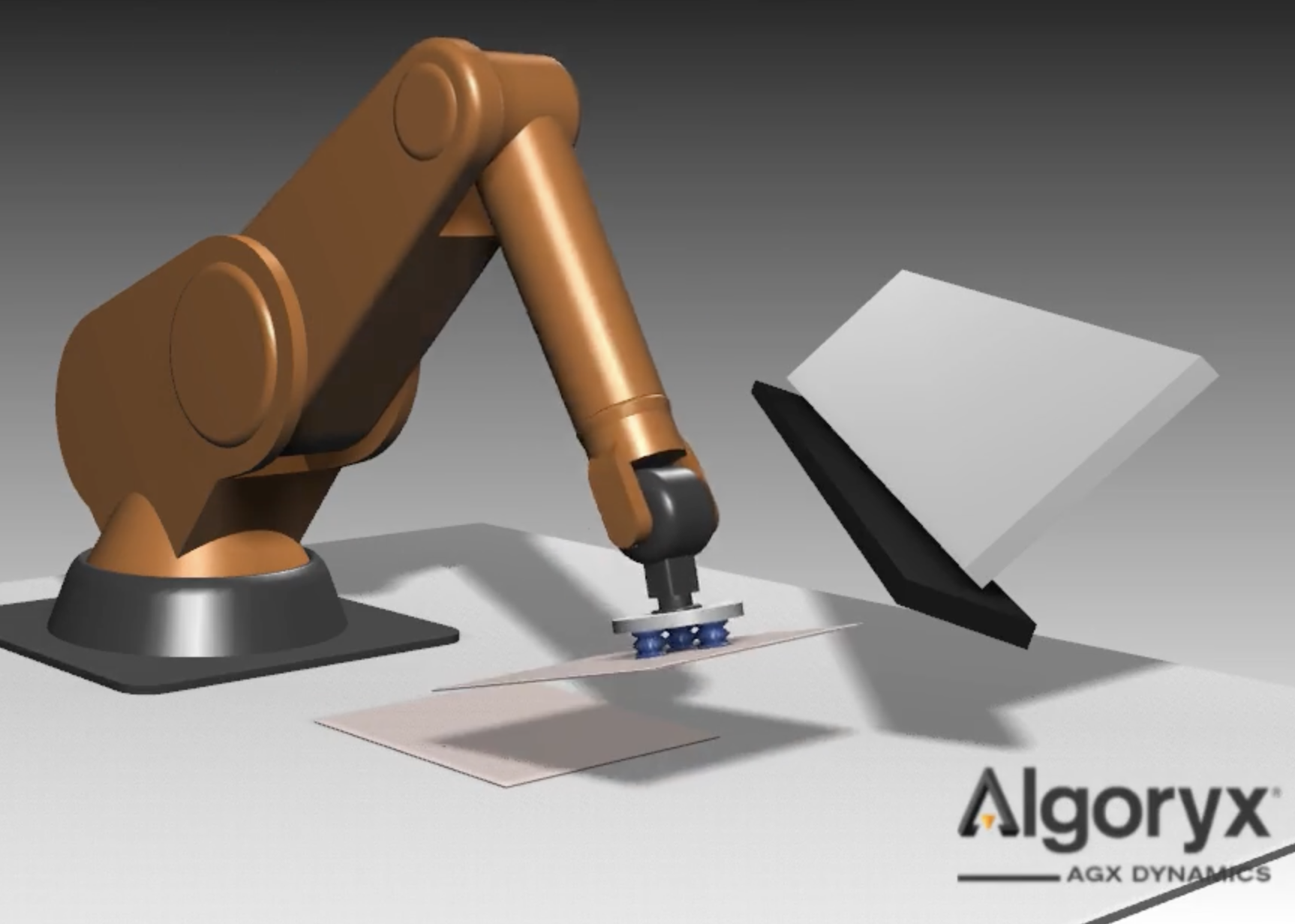
Fig. 25.1 Image capture from data/python/tutorials/tutorial_custom_suction_gripper.agxPy
The agxModel::SuctionGripper is based on the agxSDK::Assembly class which makes it possible
to model the relative suction cup positions in a local coordinate system.
The SuctionGripper requires a internal holder rigid body to be set. Its purpose is for mounting suction cups and for connecting the gripper to, for example, a robot.
// Create SuctionGripper
agxModel::SuctionGripperRef suctionGripper = new agxModel::SuctionGripper();
// Create holder rigid body, which suction cups should be attached to
agx::RigidBodyRef holderBody = new agx::RigidBody("MyHolderBody");
suctionGripper->setHolderRigidBody(holderBody);
The heart of the SuctionGripper implementation lies in the collision detection handling for each individual suction cup and their one or more sensors. Each cup interaction will generate SuctionCupInteraction’s which include information for a VacuumSystem algorithm to base its vacuum force distribution.
It is possible to inherit from the agxModel::VacuumSystem, agxModel::SuctionCup
or the agxModel::SuctionCupInteraction to customize the default behaviour.
class MyVacuumSystem : public agxModel::VacuumSystem {
  // ..
};
// Replace VacuumSystem
suctionGripper->setVacuumSystem(new MyVacuumSystem());
25.4.1. Vacuum System
The purpose of the vacuum system is to maintain a desired vacuum for all SuctionCup’s for one SuctionGripper. The desired vacuum level is set:
// Create vacuum system with desired vacuum level at 20% vacuum (80% of atmospheric pressure)
agx::Real desiredVacuum = agx::Real(0.2)
agxModel::VacuumSystemRef vacuumSystem = new agxModel::VacuumSystem(desiredVacuum);
// The desired vacuum can't be >= 1 (100% is perfect vacuum)
vacuumSystem->setDesiredVacuum(agx::Real(0.4));
The internal state for the VacuumSystem can be tuned in the following way:
// Disable the pump (enabled by default).
vacuumSystem->setEnablePump(false);

// Set the outside pressure in Pascal (atmospheric pressure by default)
agx::Real pressureOnMars = agx::Real(610);
vacuumSystem->setOutsidePressure(pressureOnMars);

// Set the outside gas density (by default set to 1.225 [kg / m^3])
agx::Real gasDensityOnMars = agx::Real(0.02);
vacuumSystem->setOutsideGasDensity(gasDensityOnMars);
For a custom VacuumSystem there are two virtual functions to consider implementing.
// This virtual function is responsible for calculating the actual force a suction cup can apply to objects, given the current situation.
// Could consider for example current leakage near the cup.
virtual agx::Real MyVacuumSystem::calculateAvailableVacuumForce(agxModel::SuctionCup* cup) override {

// This virtual function for updating the vacuum system.
// Which allow for a dynamic vacuum system.
// The default system however will toggle between desired vacuum and zero vacuum, depending on if the pump is enabled.
virtual void MyVacuumSystem::step(const agx::Real& dt, const SuctionGripper* gripper) override {
25.4.2. Suction Cup Interaction
The data contained in a SuctionCupInteraction is only valid throughout the time step. The after the collision detection stage in AGX one SuctionCupInteraction is activated for each rigid body the suction cup sensors has collided with. The API available for the suction cup interactions are the following:
// Directly after the collision detection we can go through the active interactions of one suction cup
for( auto interaction : cup->getActiveInteractionsVector() ) {

  // Interacting rigid body which will be affected by the vacuum force.
  agx::RigidBody* rigidBody = interaction->getRigidBody();

  // How many seal sensors the rigid body is interacting with
  size_t sealCount = interaction->getSealCount();

  // True if the object collides with the line sensor, located along the suction cup normal.
  bool centered = interaction->getCentered();

  // The distance to the closest point on the colliding rigid body along the center vector.
  agx::Real centerDistance = interaction->getCenterDistance();

  // The surface normal at the closest point of the colliding rigid body.
  agx::Vec3 surfaceNormal = interaction->getCenterNormalWorld();

  // The world position where the vacuum force will apply a wrench.
  agx::Vec3 worldForcePosition = interaction->getFoundSurfacePositionWorld();
}
After AGX has stepped the DynamicsSystem, forces and velocities are updated, and the following API calls are valid for examining the state of the interaction
// Directly after the collision detection we can go through the active interactions of one suction cup
for( auto interaction : cup->getActiveInteractionsVector() ) {

    // Last scalar vacuum force applied to the rigid body of the interaction
    agx::Real lastScalarForce = interaction->getCalculatedScalarForce();

    // Last directional vacuum force applied to the rigid body of the interaction
    agx::Vec3 lastDirectionalForce = interaction->getCalculatedForce();

    // Sum of all friction forces between the suction cup and the rigid body
    agx::Vec3 lastFrictionForce = interaction->getCurrentFrictionForce();

    // The total normal force between the suction cup and the rigid body
    agx::Vec3 normalForce = interaction->getCurrentContactNormalForce() const;

    // The maximal relative velocity between the suction cup and the rigid body considering all contact points.
    agx::Real relativeVelocity = interaction->getCurrentRelativeVelocity();
}
For a custom SuctionCupInteraction there is one virtual function to consider implementing.
class MySuctionCupInteraction : public agxModel::SuctionCupInteraction {
  // ..
};
// Virtual function responsible for updating the actual forces to apply to the interacting rigid body
// by calling this->setCalculatedScalarForce() and this->setCalculatedForce()
virtual agx::Real MySuctionCupInteraction::updateVacuumForce(const SuctionCup* cup, const VacuumSystem* vacuumSystem, const agx::Real& fraction) override {
25.4.3. Suction Cup
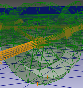
The SuctionCup require one rigid body to be valid. The SuctionCup comes with built in handling of two types of sensors, seal (Spheres) and Line. The purpose of the sensors are to detect nearby geometries of dynamic rigid bodies and create SuctionCupInteraction’s to contain all important information for vacuum forces to be computed.
The Line sensor is attached to each suction cup by default. The suction cup can be equipped with seal sensors, which help detecting if the interaction is sealed or not and will help defining a leakage area. It is up to the ::calculateAvailableVacuumForce function of the vacuum system to consider using a leakage area or not.
The local x-y plane for the suction cup rigid body define the suction cup plane. If seal sensors are used these are placed in this plane at lipRadius distance from the body origin. It is expected that the user constrains the cup body to the holder body, but it is not forced in any way.
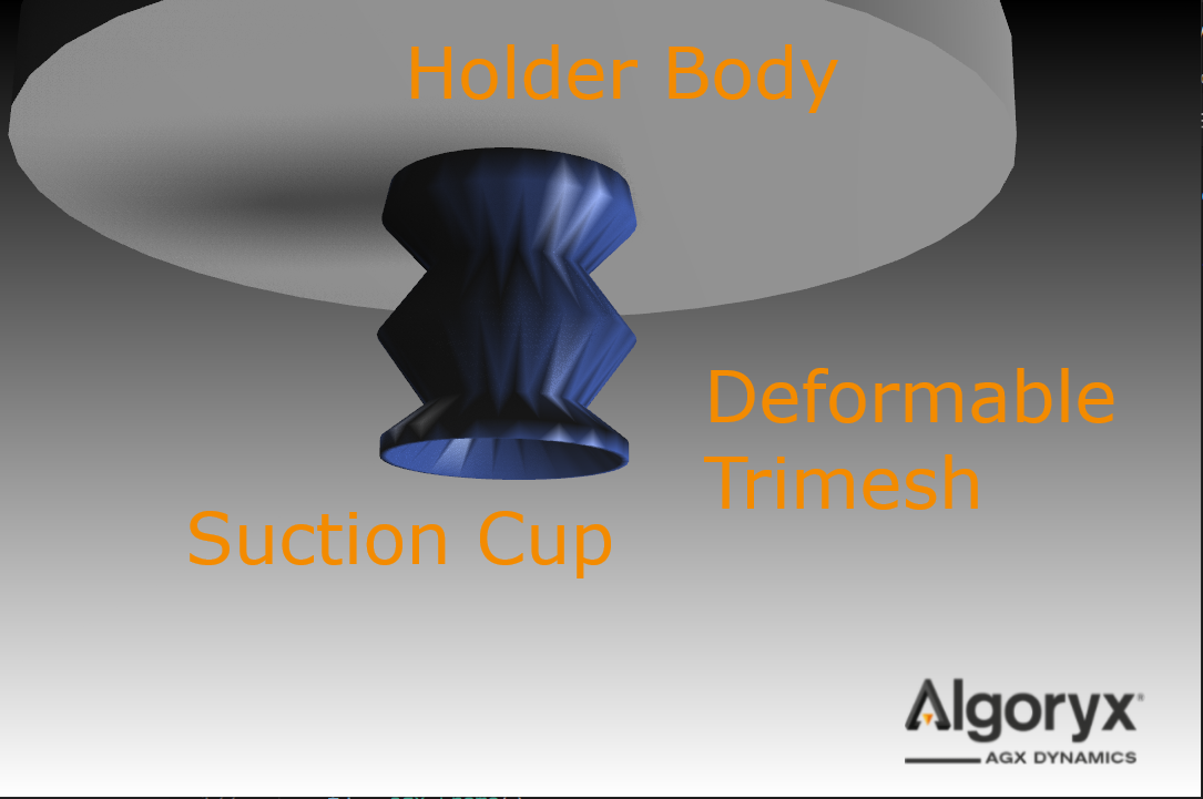
Fig. 25.2 The suction cup attached to the holder
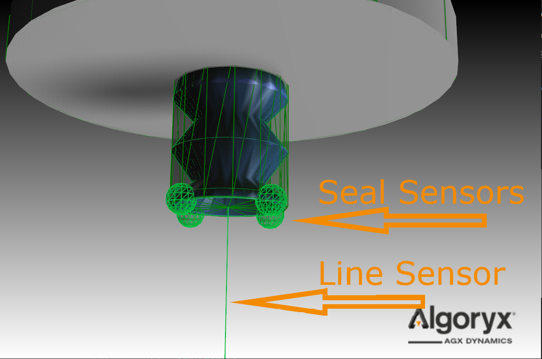
Fig. 25.3 Four seal sensors positioned in the suction cup local plane, at lip radius distance from the center.
If no rigid body is added to the constructor, a default rigid body is created.
The default rigid body will get a cylindrical collision geometry using the lipRadius and lipHeight for dimensions.
All suction cup rigid bodies will by default be given a agxCollide::Line shape geometry sensor.
There are multiple ways to customize the suction cup on creation:
// Go with the default body
agx::RigidBody* cupBody = nullptr;
// Lip radius, which define the area for the cup interaction, and therefore the maximum vacuum force
agx::Real lipRadius = agx::Real(0.025);
// Lip height, the height of the default collision geometry.
agx::Real lipHeight = agx::Real(0.01);
// How many spherical sensors you like on the circumference of the lip.
size_t sealResolution = size_t(4);
// Reach of the line sensor
agx::Vec3 lineSensorVector = agx::Vec3(0,0,-0.1);
// Radius of the seal senors spheres
agx::Real sealSensorReach = agx::Real(0.01);
agxModel::SuctionCupRef cup = SuctionCup( cupBody, lipRadius, lipHeight, sealResolution, lineSensorVector, sealSensorReach);
There is one variable to customize during runtime:
// Define a mounting radius > 0, defaults to half of the lip radius
// Will effect the pressure drop at the lip when the lip is not sealed.
agx::Real mountingRadius = 0.01;
cup->setMountingRadius(mountingRadius);
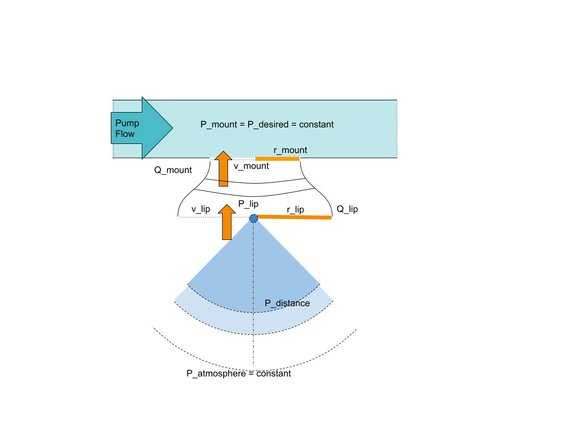
Fig. 25.4 Describe the vacuum system and how the pressure at the lip and nearby is modeled.
The default Vacuum system model a constant vacuum at the mount. The pressure at the lip \(P_l\) when there is leakage dropps according to Bernoulli’s principle, assuming constant flow \(Q_{l} = Q_{m}\) and zero air speed far away from the lip.
We define the velocity relation between the air speed at the mount \(v_m\) and the air speed at the lip \(v_l\).
We find the air velociy at the mount from Bernoulli’s principle given the pressure at the mount \(P_m\), air density \(\rho_{air}\), atmospheric pressure \(P_a\) and assuming zero air velocity far away from the cup.
Pressure drop at the lip then comes from the calculated air speed at the lip:
The pressure gradient decay quadratically relative to the distance from the suction cup center. This from assuming the flow is constant at every imaginary half sphere away from the cup.