23. AGX Terrain
agxTerrain is a library of classes that is used to model a wide variety of earthmoving scenarios such as bulldozing,
wheel loading, excavation, trenching and clamshell bucket excavation. It also supports moving the excavated soil on dump vessels. The deformable agxTerrain::Terrain
model is based on a regular 3D grid data structure and an overlapping surface height field. The terrain can be deformed by interacting agxTerrain::Shovel
objects to perform different operations, such as digging, push/pull and grading.

The underlying terrain data model consists of a 3D grid of cells, containing terrain data such as mass, compaction and soil type information. The terrain surface is represented as a 2D height field that is updated when the underlying grid structure is changed, mainly through excavation. The terrain model z-coordinate has a lower bound given by the specified maximum depth. Usually, the maximum depth is uniformly enforced on the entire terrain model but it is possible to configure a terrain with variable minimum heights.
Mass is moved in the terrain via interacting agxTerrain::Shovels that converts solid cells to dynamic mass in the form of
soil particles with 6-degrees of freedom. The dynamic soil is pushed via the shovel through kinematic coupling. A mass aggregate
body is constructed from the dynamics mass in failure zones predicted from soil mechanics theory using terrain material properties.
These aggregates create a resistance to the shovel due to their inertia, acting through contacts in the soil failure plane.
The dynamic soil is merged back into the terrain when approaching a steady state on the terrain surface.
Python tutorials and examples can be found in the data/tutorials/agxTerrain folder of the AGX Dynamics installation. Please consult the FAQ section to get answers to commonly asked questions.
This User Manual section focus on the practical application of the terrain module. We refer to the academic paper 1 for a more in-depth explanation of the underlying mathematical and physical models.
agxTerrain::Terrain height changed data can also be recorded to a journal.
23.1. Workflow
The main classes that the user interacts with when working with agxTerrain is as follows:
|
The deformable terrain object. |
|
Shovel object that converts solid mass in an |
|
Object that holds material properties used to characterize soil behavior such as compaction, soil particle dynamics and bulk properties. |
|
Object that holds generic terrain properties such as disable/enable for different features and locking terrain borders. |
|
Interface for controlling the soil simulation governing dynamic soil behavior. |
|
Controller for accessing and controlling the underlying terrain data on grid element level. |
The overall work flow for setting up a terrain model is as follows:
Create a agxTerrain::Terrain object from resolution data or an existing height field.
Create and configure agxTerrain::Shovel objects by specifying a shovel body, cutting edge, top edge and cutting direction.
Configure the Terrain Material Configuration. For example, change the default
agxTerrain::TerrainMaterialand specify other soil type domains.Setup contact materials between the terrain and external objects, especially the shovel-terrain contact materials.
Calibrate excavation resistance by configuring shovel-terrain contact material and soil properties.
(Optional) Modify the terrain properties via the
agxTerrain::TerrainPropertiesclass.(Optional) Modify the terrain grid structure using the
agxTerrain::TerrainGridControlclass.(Optional) Configure the dynamic soil.
23.2. Terrain
agxTerrain::Terrain is the main class of the agxTerrain library and represents the actual deformable terrain object. It
supports the following features:
Soil excavation using
agxTerrain::Shovelobjects.Soil compaction from either shovels or other external objects, such as for example wheels, tracks or other rigid bodies.
Conversion between solid and dynamic mass during excavation.
The underlying terrain data model consists of a regular 3D grid of cells. Terrain data such as mass, compaction and soil type information is stored discretely in each cell. The terrain surface is represented as a 2D height field that is updated when the underlying grid structure is changed, mainly through excavation. Excavation is allowed in the terrain down unto the maximum depth of the model, specified upon creation. The specified maximum depth effectively sets a uniform lowest allowable height of the surface in the terrain model. The model can also be configured to use variable minimum heights at each 2D-coordinate.
Some terrain data, such as terrain height, is parametrized by specifying only the 2D x and y coordinate, called terrain index,
which references a single discrete surface grid point on the terrain. The origin (x:0, y:0) is in the lower leftmost
gridpoint and the maximum coordinate in the upper rightmost gridpoint ( x: resolutionX-1, y: resolutionY-1 ).
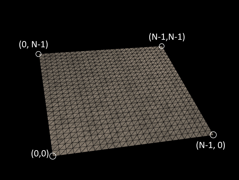
Fig. 23.1 Figure showing the index mapping of the agxTerrain::Terrain gridpoints. The origin (x:0, y:0) is in the lower leftmost
gridpoint and the maximum coordinate in the upper rightmost gridpoint ( x: resolutionX-1, y: resolutionY-1 )
Other terrain data, such as compaction, might need the full 3D x-, y-, and z-coordinate, called voxel index, to be accessed.
Note
Terrain indices and voxel indices use the same x- and y-coordinates. However, x- and y-coordinates are greater than or equal to 0, whereas the voxel index z-coordinate can be negative.
23.2.1. Terrain Setup
An agxTerrain::Terrain object can either be created by specifying the 2D size and resolution data or by using an existing
height field to define the surface level of the model. The data cells in the terrain is symmetric by design which means that the user is constrained to setting
resolution and cell size to ensure that we have a valid data structure.
Note
It is also possible to create a terrain using an arbitrary geometry via the Terrain Pager.
The following code can be used to create a terrain by specifying the 2D size and resolution data:
// Construct a Terrain with 51-by-51 elements with element size 0.2 m
// and a maximum depth of 2.5 m and it to the simulation
size_t resolutionX = 51;
size_t resolutionY = 51;
agx::Real elementSize = 0.2;
agx::Real maximumDepth = 2.5;
agxTerrainRef terrain = new agxTerrain::Terrain(resolutionX, resolutionY, elementSize, maximumDepth);
sim->add(terrain);
The resolution parameters defines the number of discretized grid cells in the X and Y axis. The elementSize sets the uniform size of
the 3D grid cells in the terrain structure. The total length of the terrain in the x- and y-axis will thus become (resolutionX-1) * elementSize and (resolutionY-1) * elementSize respectively.
The maximumDepth parameter, defines the maximum depth below the z = 0-height that the terrain can have in its local z-direction. This is equivalent to the lowestAllowedHeight in the terrain. Below this depth the terrain contains no solid mass which can be converted to dynamic mass.
Note
Sometimes the user may not want a uniform depth in the terrain, such as when trying to adjust the terrain to fit on top of a vehicle’s dump body which may not be entirely flat. To accommodate for this, it is possible to set a minimum height in each grid cell. For the purpose of dump bodies, there is a utility function Terrain::createTerrainBedFromGeometries which fits a terrain object on top of a collection of geometries. See the tutorial data\python\tutorials\agxTerrain\tutorial_dump_vessel.agxPy for a demonstration. It is also possible to manually set the heights, see the tutorial data\python\tutorials\agxTerrain\tutorial_minimum_heights.py for how to modify the minimum heights in a larger terrain.
Creating a terrain object from an existing height field is done by using the following method:
agxCollide::HeightFieldRef heightField = ... // Create the height field
// Supply height field object and a maximum depth in meters for the terrain
agxTerrain::TerrainRef terrain = agxTerrain::Terrain::createFromHeightField(heightField, 0.5);
Warning
The specified height field must have symmetric scale. I.e. the distance between vertices in x-direction must be the same as in y-direction. An agx::LOGGER_WARNING will tell you if you have an asymmetrical height field scale and a nullptr will be return from the function.
Below follows some common operations on the terrain to access data:
size_t res = 51;
agxTerrainRef terrain = new agxTerrain::Terrain(res, res, 0.2, 2.5);
sim->add(terrain);

// Returns the local height of the terrain at the lower left corner
terrain->getHeight(0,0);

// Returns the surface world position of the terrain at upper right corner index 50,50
terrain->getSurfacePositionWorld(res-1,res-1);
23.3. Shovel
Note
Only agxTerrain::Shovels can perform excavation and digging operations in the Terrain. Note that terrain compaction can be performed by all bodies.
agxTerrain::Shovel objects are used in order to deform the terrain. A shovel is an object that can represent different types of
tools used in earthmoving operations: excavator bucket, wheel loader bucket and a bulldozer blade. The shovel deforms the terrain
during digging and deformation operations that creates failure/active zones that converts solid mass in the terrain to dynamic mass. The shovel experiences
feedback forces from penetration resistance and soil aggregates that are generated from the
masses in the active zones. The shovel can also compress the soil when no excavation is in progress.
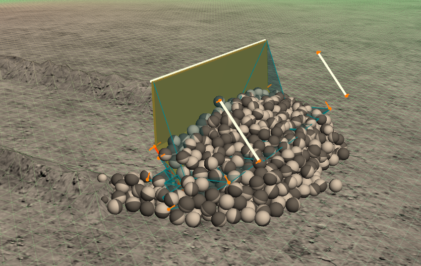
Fig. 23.2 Figure of a simple two-body agxTerrain::Shovel digging in a agxTerrain::Terrain object, converting solid mass to dynamic soil particle mass in the active zone ( light blue wedges in front, to the side and in the back of the shovel ).
A shovel can deform the terrain via the following applications:
Digging |
This is done by driving the shovel in the cutting direction into the terrain, converting solid mass to dynamic mass. See Fig. 23.3 left. |
Push/Pull |
This is done via doing push/pull operations with the sides or backside of the shovel. See Fig. 23.3 middle. |
Grading |
This is moving the soil using the backside of the shovel. See Fig. 23.3 right. |
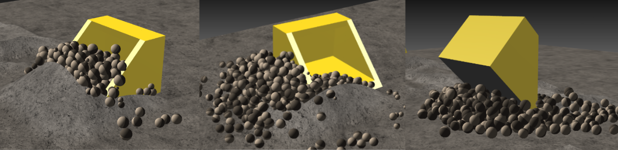
Fig. 23.3 Figure showing the different excavation operations of a shovel.
agxTerrain also support special composite shovels such as Clamshell buckets.
23.3.1. Shovel Setup
A shovel is created from a rigid body model of the shovel using a different set of vectors. A top edge, cutting edge and cutting direction
needs to be specified by the user in local body coordinates and should coincide with the geometry. Both simple box geometries and more complex
mesh shapes can be used.
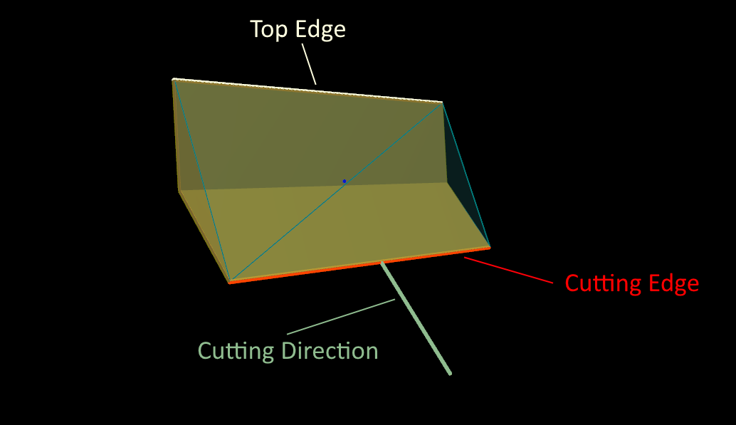
Fig. 23.4 Figure of the basic components needed in order to create a shovel. A Rigid body representing the shovel object. A top edge is placed on
the upper confines of the expected digging area, a cutting edge is placed on the lowest confines of the digging are and a cutting direction
is placed along the expected cutting direction of the shovel which is parallel to the bottom plate of the shovel.
The placement of the vectors should be as described below and visualised in Fig. 23.5:
The
top edgeshould ideally be placed at the upper confines of the cross-sectional digging area.The
cutting edgeshould coincide with the lowest edge of the shovel that is expected to initially cut the soil. It should be placed at the base of the shovel teeth geometry of they exist.The
cutting directionshould be placed along the direction of the bottom plate of the shovel.
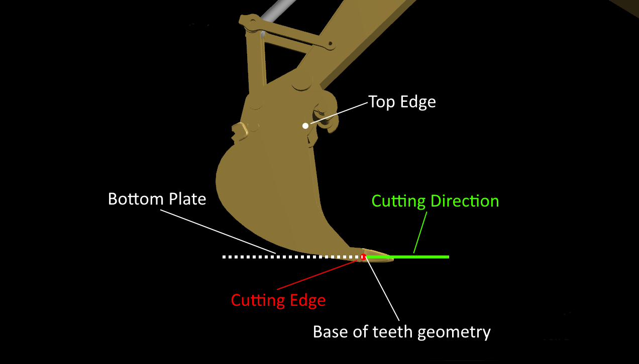
Fig. 23.5 Figure showing the shovel vector placement for an excavator bucket. The cutting direction should be placed parallel to the bottom
plate of the shovel. The cutting edge should be placed at the tip of the shovel and the base of the teeth geometry.
A shovel is created via the following constructor and then added to the simulation:
agxTerrain::ShovelRef shovel = agxTerrain::Shovel( agx::RigidBody* shovelBody,
                                                   const agx::Line& topEdge,
                                                   const agx::Line& cuttingEdge,
                                                   const agx::Vec3& cuttingVector );
simulation->add(shovel)
See shovel settings for various options that is used to modify shovel behaviour.
After a shovel has been added to a simulation, it will interact with any other terrains added to the simulation. This also includes any terrains used as movable terrain. It is possible to disable shovel<->terrain interactions between specific pairs of shovels or terrains. Example:
// Disable terrain interactions - excavation, bulldozing, etc - with a specific shovel
bool enable = false;
shovel->setEnableForTerrain(terrain, enable);

// Also disable geometry contacts, ie collisions between the shovel and the terrain
shovel->setEnableShovelTerrainGeometryContacts(terrain, enable);
23.4. Movable Terrain
It is possible to use a terrain as part of a dynamic, movable rigid body. This is especially useful if the user wishes to model dump trucks or other vessels used for moving excavated soil between locations. To attach a terrain to a rigid body, use the following code snippet:
void attachTerrainToRigidBody(agxTerrain::Terrain* terrain, agx::RigidBody* rb)
{
  rb->add(terrain->getGeometry());
}
To make it easier for the user to fit terrain objects to rigid bodies, there is a utility function Terrain::createTerrainBedFromGeometries which works on a list of geometries. If your rigid body simply is a platform, the following code snippet may suffice:
// Create a terrain bed from the geometries in a rigid body with resolution 16 along the x-axis. The resolution along the y-axis will be approximated from the dimension of the given geometries.
auto bedTerrain = createTerrainBedFromGeometries(16, rb->getGeometries());
It is also possible to create a dump vessel which during tipping turns the offloaded soil on the bed into dynamic mass, which then can be redeposited into the ground. This is also showcased in data\python\tutorials\agxTerrain\tutorial_dump_vessel.agxPy, where a StepEventListener is used to turn solid mass into dynamic mass when the dump bed has been tipped over a certain angle. A visualization of a terrain used as a dump bed and the tipping can be seen below in Fig. 23.6:
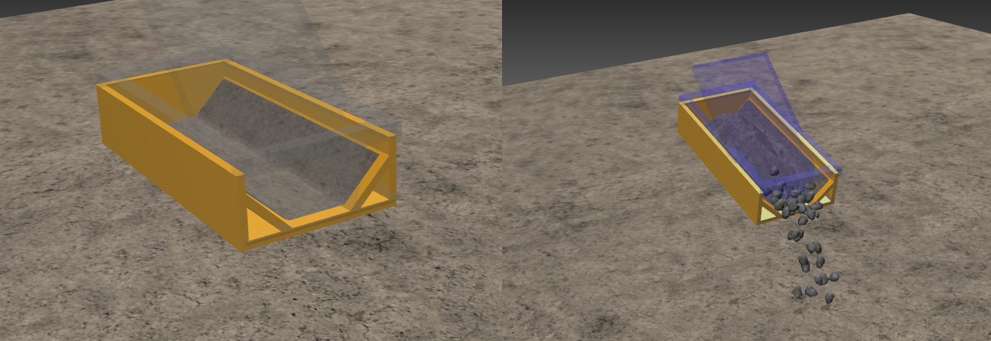
Fig. 23.6 Figure showing the example dump bed modeled in tutorial_dump_vessel.agxPy. To the left, an empty offload terrain attached to the rigid body. To the right, a partially filled dump bed during tipping.
Note
Modeling tipping, where the solid mass in the dump bed is turned into dynamic mass, has some caveats. For example, the user must make sure the same terrain material is used both in the bed and in the ground, otherwise mass conservation is not assured. Likewise, soil repose effects are not properly represented in a tilted agxTerrain::Terrain during tipping, as the objects local z-axis and the gravity direction does not align during that time.
23.5. Terrain Material Configuration
The agxTerrain::TerrainMaterial objects govern internal terrain behaviour and contains dynamic soil interaction parameters, internal soil contact parameters, angle of repose, compaction, etc, which may vary depending on soil type.
The agxTerrain::Terrain holds a default agxTerrain::TerrainMaterial, which applies everywhere unless other soil types are added.
There are get/set methods for interacting with the default agxTerrain::TerrainMaterial:
// Get the currently assigned default terrain material
agxTerrain::TerrainMaterialRef defaultTerrainMaterial = terrain->getTerrainMaterial();

// Create a new TerrainMaterial with default parameters, and set it as the default terrain material
agxTerrain::TerrainMaterialRef terrainMaterial = new agxTerrain::TerrainMaterial()
terrain.setTerrainMaterial(terrainMaterial)
It is also possible to add several other agxTerrain::TerrainMaterial to the terrain, representing different soil types in different regions. To do this, use the addTerrainMaterial method:
agxTerrain::Terrain::addTerrainMaterial(agxTerrain::TerrainMaterial* terrainMaterial);
agxTerrain::Terrain::addTerrainMaterial(agxTerrain::TerrainMaterial* terrainMaterial, agxCollide::Geometry* geometry);
The first method only adds the terrain material to the terrain, without assigning it to any area. The second method adds the terrain material to the overlap between the terrain and the geometry. This is the part of the terrain below the height field and the geometry that intersects.
If a terrain material has been added, it can be removed entirely, together with any domain assignment, with the removeTerrainMaterial method:
agxTerrain::Terrain::removeTerrainMaterial(agxTerrain::TerrainMaterial* terrainMaterial);
If the user wants to keep the assigned domain but simply change the material, there is a method for that as well:
bool agxTerrain::Terrain::exchangeTerrainMaterial(TerrainMaterial* oldTerrainMaterial, TerrainMaterial* newTerrainMaterial);
Note
The default terrain material can not be removed, but it can be exchanged.
agxTerrain::TerrainMaterial properties can be configured according to the desired effects. There is also pre-calibrated material presets
for the agxTerrain::TerrainMaterial objects to choose from, if you do not wish to specify their properties manually. The user can also specify their own presets.
All preset materials can be found under the data/MaterialLibrary/TerrainMaterials in the AGX Dynamics installation folder.
Note
We recommended that new users start with a material preset as a starting point before manually configuring their own TerrainMaterial.
Refer to the agxTerrain::TerrainMaterial section to get an overview of all available soil parameters.
23.6. Setup Contact Materials
There are 5 types of interactions that the terrain can have:
|
This is the interaction between the shovel and the terrain that happens via aggregate formation during excavation and deformation. The contact parameters here are derived from the contact materials specified between the shovel and the terrain. See calibration of excavation resistance. |
|
This is the interaction between the terrain and external objects such as wheels and tracks. |
|
The interaction between the dynamic soil and the external object, such as shovels and tracks. |
|
The interactions between the dynamic soil particles. |
|
The interactions between the dynamic soil particles and the terrain surface. |
Each of these interactions depend on the defined contact materials between the relevant materials.
23.6.1. Internal Materials
In the case of interactions with the terrain, every agxTerrain::TerrainMaterial in the terrain has a link to an internal associated agx::Material.
To access the associated materials with any terrain material, use the following get/set methods:
agx::Material* Terrain::getAssociatedMaterial(TerrainMaterial* terrainMaterial);
bool Terrain::setAssociatedMaterial(TerrainMaterial* terrainMaterial, agx::Material* material);
If no additional terrain materials have been added, the getMaterial method can be used to get all the relevant internal materials:
agx::Material* getMaterial(agxTerrain::Terrain::MaterialType type) const;
Where the type variable is either:
|
This is the default material set on the terrain surface. This material can be extracted and used to construct contact material parameters between the terrain ground and vehicle. |
|
The internal material for the dynamic soil particles in the terrain internal simulation. This material is used for interactions with the dynamic soil. |
The total Shovel-Terrain interaction feedback is a combination of agxTerrain::TerrainMaterial and agx::Material properties. This can be configured in the following ways:
Specifying the agxTerrain::TerrainMaterial objects in the Terrain. There are pre-calibrated material presets for the
agxTerrain::TerrainMaterialobjects to choose from, if you do not wish to specify their properties manually.Extracting the associated
agx::Materialinstances from the terrain in order to create shovel-terrain contact materials for objects interacting with the terrain. This will affect interaction force feedback with the tool.
Note
The coupling between the Shovel and the dynamics soil particles are kinematic. The force feedback on the shovel comes from contact with soil aggregates that are constructed from the particles. So the defined Shovel <-> Terrain contact materials is what is driving excavation and penetration resistance.
23.6.2. Shovel - Terrain Contact Materials
The contact materials specified between the shovel and the terrain are some of the primary determinants of excavation resistance. The contact properties are used in the shovel-aggregate contacts for all excavation modes. It is also used in regular geometry contacts between the shovel and the terrain when excavation mode is active. For each soil type added to the terrain instance there is a contact material between that soil types associated material and the shovels material.
To set up the contact material for the default part of the terrain, the following code can be used:
agx::MaterialRef shovelMaterial = new agx::Material("Shovel");
simulation->add(shovelMaterial);

// ... set the shovel material on the shovel bodies
agxUtil::setBodyMaterial(shovelBody, shovelMaterial);

agx::MaterialRef terrainMaterial = terrain->getMaterial( agxTerrain::Terrain::MaterialType::TERRAIN );
agx::ContactMaterialRef shovelTerrainCM = new agx::ContactMaterial( shovelMaterial, terrainMaterial );
shovelTerrainCM->setFrictionCoefficient( 0.4 );
shovelTerrainCM->setYoungsModulus( 1e8 );
shovelTerrainCM->setRestitution( 0.0 );
shovelTerrainCM->setAdhesion( 0, 0 );
simulation->add( shovelTerrainCM );
To set up the contact material with a part of the terrain where another soil type was added, the following code can be used:
agx::MaterialRef shovelMaterial = new agx::Material("Shovel");
simulation->add(shovelMaterial);
// Get and add a terrain material
agxTerrain::TerrainMaterial dirt = terrain->getLibraryMaterial("dirt_1");
terrain->addTerrainMaterial(dirt);
// Get the associated material
agx::Material dirtAgxMaterial = terrain->getAssociatedMaterial(dirt);
// Define the contact material between dirt<->shovel
agx::ContactMaterialRef shovelDirtCM = new agx::ContactMaterial( shovelMaterial, dirtAgxMaterial );
shovelDirtCM->setFrictionCoefficient( 0.4 );
shovelDirtCM->setYoungsModulus( 1e8 );
shovelDirtCM->setRestitution( 0.0 );
shovelDirtCM->setAdhesion( 0, 0 );
simulation->add( shovelDirtCM );
Refer to the section Terrain material configuration for a description of how to add different soil types to the terrain and the section on internal materials to configure associated materials with the terrain materials.
Note
When the shovel interacts with a part of the terrain that intersects two or more regions where there are different soil types, the contact material properties are averaged.
23.6.3. Object - Terrain Contact Materials
The Object-Terrain contact materials can be used to calibrate the interaction between the terrain and external objects such as wheels or tracks.
The code to setup these contact materials are similar to how the Shovel-Terrain contact materials
are defined. Just use the agx::Material of the object instead of the shovel!
agx::MaterialRef objectMaterial = new agx::Material("ExternalObject");
simulation->add(objectMaterial);

// ... set the object material on the external bodies
agxUtil::setBodyMaterial(externalObjectBody, objectMaterial);

agx::MaterialRef terrainMaterial = terrain->getMaterial( agxTerrain::Terrain::MaterialType::TERRAIN );
agx::ContactMaterialRef objectTerrainCM = new agx::ContactMaterial( objectMaterial, terrainMaterial );
objectTerrainCM->setFrictionCoefficient( 0.4 );
simulation->add( objectTerrainCM );
// Get and add another terrain material
agxTerrain::TerrainMaterial dirt = terrain->getLibraryMaterial("dirt_1");
terrain->addTerrainMaterial(dirt);
// Get the associated material
agx::Material dirtAgxMaterial = terrain->getAssociatedMaterial(dirt);
// Define the contact material between dirt<->shovel
agx::ContactMaterialRef objectDirtCM = new agx::ContactMaterial( objectMaterial, dirtAgxMaterial );
simulation->add( objectDirtCM );
Refer to the section Terrain material configuration for a description of how to add different soil types to the terrain and the section on internal materials to configure associated materials with the terrain materials.
Note
If the external object interacts with a part of the terrain that intersects two or more regions where there are different soil types, the contact material properties are averaged.
23.7. Calibration of Excavation Resistance
The terrain generates excavation resistance through the following effects:
Generated by digging and pushing soil in the forward digging direction. |
|
Force generated via penetration of the cutting plate in the cutting direction. |
|
Similar to the separation forces but generated during push/pull/grading operations. |
|
Generic Contact Forces |
These are the regular contact forces when no excavation mode is active. |
Note
It is recommended that the user always check their excavation forces during terrain setup. This is in order to properly asses the feasibility of the forces and phenomena that is generating feedback.
The force feedback that is generated on a shovel can be extracted by the following methods:
bool Shovel::getPenetrationForce(agx::Vec3& force, agx::Vec3& torque) const;

agx::Vec3 Shovel::getSeparationContactForce() const;

agx::Vec3 Shovel::getDeformationContactForce() const;

agx::Vec3 Shovel::getContactForce() const;
The main ways to adjust these are:
Contact properties between the shovel and the terrain aggregate. This is controlled by the contact material specified between the shovel geometries and the different soil types in the terrain instance. See contact materials. This affects both penetration resistance and separation/deformation resistance.
Terrain Material properties, such as soil density, stiffness and friction angle. This determines soil aggregate weight and also internal contact properties, i.e contacts between the aggregate and the terrain.
Adjust the penetration resistance by modifying the
PenetrationForceScalingparameter.
23.7.1. Contact material calibration
The following properties are the most relevant when calibrating the contact materials between the shovel and terrain.
|
Determines the stiffness in the shovel <-> terrain contacts. |
|
Adjusts the friction force between the shovel and terrain. |
23.7.2. Terrain Material
The following parameters determines the internal contact and shape properties of the soil aggregates. Most of them are found the in the bulk properties but some are also found in excavation contact properties. To see how to add/remove terrain materials, please refer to the section on Terrain material configuration.
|
Determines the stiffness in the aggregate <-> terrain contacts. |
|
Affects the force feedback from the terrain via setting a cohesion value in the aggregate <-> terrain contacts. Also affects the cohesion of the dynamic mass hat might lead to higher measured masses. |
|
This affects the angle of the failure zones and also determines the friction coefficient in the aggregate <-> terrain contacts. |
|
Affects the total mass of the soil aggregates formed in the shovel active zone. |
|
Scales the bulk Young’s modulus applied in the shovel <-> aggregate contact in order to allow the user to fine-tune the excavation force. |
|
Scales the bulk Young’s modulus applied in the aggregate <-> terrain contact in order to allow the user to fine-tune the excavation force. |
23.7.3. Calibration of Penetration Force
The user can explicitly control the penetration force either by apply a scaling factor or a maximum cap on the penetration force:
shovel->setPenetrationForceScaling(5.0);
shovel->setMaxPenetrationForce(10000); // In Newton
Note
The need to apply a scalar scaling factor on the penetration model is due to the fact that shovels have different geometry and cutter formation that interact in a way that the current model is unable to capture. Therefore it might be necessary to calibrate the scaling factor to achieve the desired initial breach force.
23.7.4. Suggested calibration workflow
This section provides a sample workflow for calibrating agxTerrain. This list assumes that the user has access to benchmark data from either theory or a experimental test that they wish to reproduce in agxTerrain:
First ensure that the TerrainMaterial->BulkProperties holds the same parameters as the real world soil used in the experiments. Also use values obtained from experiments and literature. Density is especially important.
Ensure that the final mass in the shovel agrees with the end mass in the test specified. This involves modifying the following bulk properties:
Update
Bulk Properties - Swell FactorThis determines how the material grows or swells after excavation, emulates de-compaction of soil into a loosely packed state.Update
Bulk Properties - Bulk density.Update
Bulk Properties - Cohesion. High cohesion values will cause the material to stick together more, creating more material in the shovel.
Calibrate the Penetration Resistance Force Scaling so that the force feedback during the initial breach agrees with measured data. Recommended start interval 10-16.
Modify BulkProperties.
Young’s Modulus.
Friction Angle.
Cohesion.
Contact material between Shovel and terrain (Suggested parameters).
Friction.
Young’s modulus.
Excavation Contact Properties (Suggested parameters, Used as a ‘last resort’).
AggregateStiffnessMultiplier.
ExcavationStiffnessMultiplier.
Note
CompactionProperties does not affect force feedback during excavation.
23.8. Terrain Paging
Terrain paging exists to solve the following problems:
One needs a large area to operate in, which results in excessively high direct memory usage.
One needs a resolution and an area that together result in excessively high direct memory usage.
There are multiple machines that need to operate on terrain simultaneously at too great a distance for a terrain to handle it (due to memory usage).
The terrain is defined in a format that does not allow for direct creation via an API in agxTerrain, for example, a triangle mesh.
This is achieved via the agxTerrain::TerrainPager class. It has a virtual 2D grid
with square tiles in which it can load in agxTerrain::Terrain instances as needed.
The Terrain instances are unloaded again when they are not needed any longer.
/**
 Constructor. Specifies tile information and the 2D-plane used for dynamic terrain tiles.

 The TerrainPager do not mirror all the different parameters a terrain exposes,
 instead a template terrain is used for settings.

 To support excavation, the terrain tiles have an optional margin. This margin can
 be set so that the excavation is performed within one tile and correct soil wedges
 are formed.

 Example: tileResolution = 301, tileOverlap 10, tileElementSize = 0.25, ....

          Each tile then becomes (301-1)*0.25 = 75m x 75m
          The overlap on each side will be 10*0.25 = 2.5m

 \param tileResolution    Specifies the number of height values for each dimension for (tile+margin).
 \param tileOverlap       Specifies the number of height values that should overlap between two tiles.
 \param tileElementSize   Size in meters for one element. Same as distance between two height values.
 \param maximumDepth      How deep in meters the terrain can be excavated
 \param referencePoint    A world reference point for where the terrain is located
 \param referenceRotation A rotation that will transform the Z-axis to the up direction at the referencePoint
 \param templateTerrain   A template terrain whose settings will be used for the terrain tiles.
 */

 TerrainPager(size_t tileResolution, size_t tileOverlap, agx::Real tileElementSize, agx::Real maximumDepth,
              agx::Vec3 refPoint, agx::Quat refRotation,
              agxTerrain::Terrain* templateTerrain );
Note
It is important that the edges of two adjacent tiles match. To handle this and support excavation, adjacent tiles can have an overlap. When excavation is performed, the soil wedges are kept within a tile and to have non-truncated soil wedges. The overlap should be larger than both the length of the cutting edge interacting with the terrain aswell as twice the expected maximum length of a soil-wedge (which depends on how deep excavation in the terrain will be performed).
Warning
Adding a Terrain instance to a Simulation will also set some Solver parameters that the terrain needs and cause the Simulation update task to be rebuilt. It is not supported to rebuild the update task when it is executing, that is, during Simulation::stepForward. It can cause Simulation::stepForward to not return.
The TerrainPager must be able to add and remove terrains during stepForward. Hence, Simulation::add( TerrainPager) prepares the Simulation by setting the same solver parameters that Simulation::add( Terrain ) would do, preventing a later task rebuild.
After a TerrainPager has been added to a Simulation, it is not supported to change any of the following solver parameters: - setUseParallelPgs - setUse32bitGranularBodySolver - setUseGranularWarmStarting Also, adding a TerrainPager to the Simulation will change the BroadPhase Algorithm used by Space to HIERARCHICAL_GRID. It is not supported to change it to SWEEP_AND_PRUNE.
23.8.1. Tracking bodies / shovels
To know which tiles that should have Terrain instances, bodies and shovels can be added to
the agxTerrain::TerrainPager for tracking.
Each tracked item have two radiuses associated with them:
The required radius: All tiles within this radius must be in the Simulation for
agxSDK::Simulation::stepForwardto be able to proceed. Can causestepForwardto wait while the tile processing occurs in the background.The preload radius: Tiles within this radius will be preloaded in the background and inserted into the Simulation when ready.
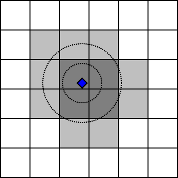
Fig. 23.7 Figure that shows a tracked item in blue, required tiles in dark gray and tiles within the preload radius in light gray. Normally the tiles are much larger than in this example image and fewer tiles are active.
The value for the required radius should be selected so that all geometries attached to the body that may interact with the terrain are enclosed within the radius. The value for the preload radius should be chosen so that tiles may be loaded into memory well before they will be needed in the simulation to avoid hiccups. This means the higher the expected maximum velocity the higher the preload radius relative to the required radius.
/**
Adds a RigidBody to the terrain pager. The pager will make sure that terrain tiles
within the required radius are present in the Simulation before stepping and tiles
within the preload radius will be loaded and inserted when available.
*/
bool add( agx::RigidBody* body, agx::Real requiredTileRadius, agx::Real preloadTileRadius );


/**
Remove body so that the terrain pager no longer uses the body when determining
which terrain tiles that are needed.
*/
bool remove( agx::RigidBody* body );
If a shovel is added to the pager, the shovels rigid body will be tracked as outlined above. The pager needs to be added to a simulation in order to register shovels.
23.8.2. TerrainDataSource
The TerrainPager must also have a TerrainDataSource from which it can request
height data for the needed tiles. The first time a tile is needed, heights are requested.
If the tile is paged out then the height values are stored to disk. If it is needed again
the possibly modified values are read from file and not requested from the data source.
There is one class that implements the TerrainDataSource interface:
agxTerrain::TerrainRasterizer. The TerrainRasterizer should be given source
geometry (e.g. large heightfield(s)) which it will then sample with raycasting to
get height values at the needed positions.
Note
When implementing a custom data source in languages other than C++ using the AGX bindings,
the ExternalTerrainDataSource class should be inherited instead of the TerrainDataSource
class and serialization of the data source is disabled
23.8.3. Paged Terrain settings
The TerrainPager do not expose the material settings for the terrain tiles. Instead, one of the arguments to the TerrainPager constructor is a template terrain. Each time a terrain tile is inserted into the simulation, the template settings are applied to the new tile.
/**
Fetches the template terrain.
The settings for the template terrain are used on new terrain tiles
when they are inserted into the simulation.

\see applyChangesToTemplateTerrain
*/
agxTerrain::Terrain* getTemplateTerrain();

/**
Signals to the TerrainPager that the template terrain has been updated
and that any changes to the template terrain should be applied to the
active terrain tiles in the pager.
*/
void applyChangesToTemplateTerrain();
Each time a new Terrain instance is inserted into the Simulation, the TerrainPager
triggers an event, tileLoadEvent, and in the same way when removing a Terrain
tileUnloadEvent is triggered. With these events it it also possible to customize
tiles settings per tile.
Compaction data for paged out tiles is not stored by default. If this is needed the method
TerrainPager::setShouldStoreCompaction( bool, size_t ) can control this and specify
how many voxels below the surface that should be stored.
Note
The amount of stored data per paged tile will increase greatly if maximumCompactionDepth is set too high.
23.8.4. Serialization
The terrain pager has two ways of serialization. There is a full state serialization using InputArchive and OutputArchive and there is a serialization of modified terrain height data.
The full state serialization use the functions
void TerrainPager::store(agxStream::OutputArchive& out) const and
void TerrainPager::restore(agxStream::InputArchive& in).
Part of the state held by the terrain pager can be paged out to disk (see
TerrainPager::setFileCacheDirectory). The files in that directory are needed along with
the serialized archive. If needed, the paged out data can be embedded in the archive. This
is controlled via TerrainPager::setEmbedCacheFilesInArchive( bool ).
Furthermore, compaction data is not stored by default. If this is needed the method
TerrainPager::setShouldStoreCompaction( bool, size_t ) can control this and specify
how many voxels below the surface that should be stored.
Note
The amount of stored data per paged tile will increase greatly if maximumCompactionDepth is set too high.
The serialization for the changed heights uses the methods
void TerrainPager::store( agxTerrain::TileModificationVector& storeData );
void TerrainPager::restore( const agxTerrain::TileModificationVector& restoreData );
this is described in more detail below.
23.8.5. Store / restore of terrain height data
There are custom store/restore functions which can be used for serialization of paged terrains heights if needed.
If TerrainPager::setShouldStoreDeltas is enabled, then terrain pager will start collecting height
changes internally. Unless these values are fetched periodically, the internal structure
will keep growing. These delta changes can be fetched via
void TerrainPager::store( agxTerrain::TileModificationVector& storeData );.
The output is written to storeData and will contain the changes since last time the
function was called. After store has been called, the TerrainPager will clear its
internal buffer with changes.
To restore the system, void TerrainPager::restore( const agxTerrain::TileModificationVector& restoreData ); should be used.
The restoreData should be the aggregated state from all the store deltas.
This will give the terrain pager a set of changes which should be applied to a tile after
the height data has been requested from the terrain data source.
23.8.6. Terrain paging tutorials
A full example of how the TerrainPager and TerrainRasterizer can be used
along with dynamic loading/unloading of Terrain tiles can be seen in
data/python/agxTerrain/basic_paging_example.agxPy.
There is also an example which uses a kinematic body to
control which tiles that are preloaded and performs
efficient raycast measurements of the terrain height
data/python/agxTerrain/paging_depth_measurements.agxPy.
There is also a tutorial showing bulldozing with a terrain pager
data/python/agxTerrain/tutorials/agxTerrain/tutorial_bulldozing_terrain_paging.agxPy.
23.9. Composite Shovels
This section covers the usage of special shovel constructions that is not covered by the standard shovel model. These types of tools are often are represented with two or more interacting shovels that requires synchronization.
23.9.1. Clamshell Bucket
agxTerrain support the simulation of Clamshell buckets which are a two-sided, hinged buckets
used in earthmoving and material handling operations such as dredging, construction and bulk
material handling. The bucket often operates using hydraulic cylinders or mechanical cables
that open and close the shells. It can be attached to cranes, excavators, or other lifting machines.
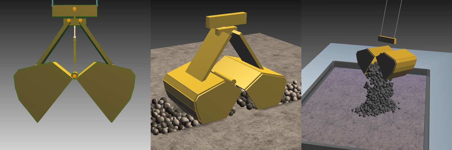
Fig. 23.8 Figure that demonstrates the construction and operation of a ClamShellBucket. Left image shows a basic layout of the construction of two hinged buckets that opens and closes via a central prismatic joint. Middle image shows a excavation operation where the clam shell is in the closing stage before extracting soil material. The right image shows an unloading operation of a crane steered clam bucket where bulk material is unloaded on top of a dump terrain after excavation.
In order for the internal terrain calculations to work properly for a clam shell construction
an agxTerrain::ClamShellBucket object needed used to connect the soil aggregates of both shovels
when they are in a closed state:
// Create the clam shell object that will handle the internal terrain logic
// of connecting the soil aggregates when the buckets are closed.
agxTerrain::ClamShellBucketRef clamShellBucket = new agxTerrain::ClamShellBucket( bucket1, bucket2 );

// The threshold distance between the two shovel cutting edges under
// which the clam shell is considered in closed state.
clamShellBucket->setClosedThreshold(0.1) // in meters

// Add the bucket to the simulation
simulation->add(clamShellBucket)
Note
Note that the agxTerrain::ClamShellBucket class does not handle the mechanical construction of the bucket, that needs to be done
via modelling via constraints and rigid bodies.
For an example of a crane steered Clamshell Bucket in an excavation scenario,
see data/python/tutorials/agxTerrain/tutorial_clamshell_bucket.agxPy.
23.10. Forbidden bounds
It is possible to add bounding volumes based on the agxTerrain::IForbiddenBound interface
in either positions or local terrain index coordinates to agxTerrain::Terrain objects
that prevents avalanching and merging of particles into the terrain indices that overlap the
bounds. The following snippet shows how to add a bound based on local terrain index:
agxTerrain::TerrainRef terrain = new agxTerrain::Terrain( 51, 51, 0.1, 2.5 );
simulation->add( terrain );

// Add a 3D index bound to the terrain that covers the left half of the terrain.
agxTerrain::IForbiddenBoundRef ib = new agxTerrain::ForbiddenIndexBound( agx::Bound3i( agx::Vec3i( 0, 0, -5 ),
                                                                                       agx::Vec3i( 25, 51, 5 ) ) );
terrain->addForbiddenBound( ib );
Spatial 3D bounds can also be created and attached to the frames of bodies and geometries so that they can follow the object’s transform:
// Add a moving rigid body
agxCollide::GeometryRef box_geom = new agxCollide::Geometry( new agxCollide::Box( agx::Vec3( 0.25, 0.25, 0.25 ) ) );
agx::RigidBodyRef rb = new agx::RigidBody( box_geom );
simulation->add( rb );

// Add a 3D forbidden bound attached to the frame of the rigid body.
// Add a local transform offset for rotation and position to the bound
agx::AffineMatrix4x4 localTransform( agx::EulerAngles( 0, 0, agx::PI/4.0 ), agx::Vec3( 0, 0, -0.5 ) );
// Create the bound and use the agx::Frame of the RigidBody as the parent transform via rb->getFrame
agx::Vec3 halfVec( 0.5, 2.5, 0.5 );
agxTerrain::IForbiddenBoundRef fb = new agxTerrain::ForbiddenBound( agxCollide::BoundingAABB( -halfVec, halfVec ),
                                                                    localTransform,
                                                                    rb->getFrame());
terrain->addForbiddenBound( fb );
Bounds can also be removed from the terrain:
agxTerrain::IForbiddenBoundRef fb = new agxTerrain::ForbiddenBound ...
terrain->addForbiddenBound(fb)
...
terrain->removeForbiddenBound(fb)
23.11. Terrain agxJournal support
agxTerrain::Terrain height data changes during a simulation can be stored to an agxJournal file and be replayed during journal playback.
The agxTerrain::TerrainJournalRecorder class can be used to record the terrain height data to a journal
file during journal recording and automatically restore it during playback:
agxTerrain::TerrainJournalRecorderRef recorder = new agxTerrain::TerrainJournalRecorder(terrain);
simulation->add(recorder);
Note that an argument can be supplied when running a terrain script via ExampleApplication that automatically adds this class for each terrain object in the simulation.
python myTerrainScript.py --journalRecord --terrainJournalRecord
agxViewer myTerrainScript.agxPy --journalRecord --terrainJournalRecord
23.12. Terrain Model
This section contains model descriptions of the different parts in the agxTerrain::Terrain object.
23.12.1. Terrain Grid Structure
The terrain data is stored in an underlying 3D grid structure. Each gridpoint contains the following information:
Solid Mass occupancy
Soil Compaction
Terrain Material information
Surface terrain data, such as terrain height, is accessed by specifying a terrain surface index, which references a single discrete surface grid point on the terrain.
The terrain surface index consists of 2D x and y coordinates with origin (x:0, y:0) in the lower leftmost gridpoint and the maximum coordinate in the upper rightmost
gridpoint ( x: resolutionX-1, y: resolutionY-1 ) in the terrain surface structure.
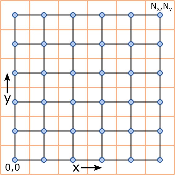
Fig. 23.9 Figure that shows the indexing and grid layout of the agxTerrain in the x/y surface plane. The blue points denote grid center
points that coincide with the surface heightfield vertices. The orange grid denotes the cell boundaries. The indexing starts
in the lower left corner with x:0,y:0 and goes to the upper right corner x:resolutionX-1, y:resolutionY-1.
To access full spatial data, a 3D grid coordinate (x,y,z) is specified using the same 2D surface index as above but also with an added depth index.
The origin of the depth index is defined where the surface height of the terrain is zero, and the lowest allowable z index corresponds to the maximum depth of the terrain.
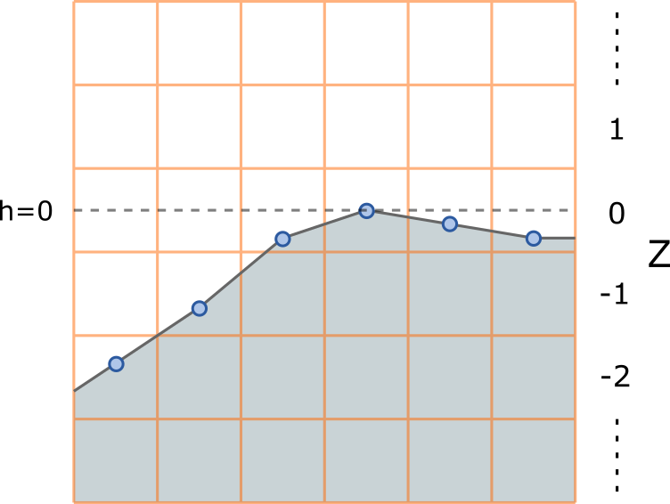
Fig. 23.10 Figure that illustrates the layout of the depth index in the terrain cell structure via cross-section view in the x/z plane. The orange grid shows the cell boundraries in the terrain structure and the blue points shows the height field vertex height positions. The local terrain center z position of the grid cell with depth index 0 is defined where the height of the coupled heightfield is zero.
A uniform maximum depth is default configuration for the terrain model, but the terrain can be configured to use specific minimum heights in each terrain index with the following functionality:
/*
\return bool indicating whether the terrain should use minimum heights instead of uniform maximum depth.
*/
bool getEnableMinimumHeights() const;

/*
Enable (true) or disable (false) the usage of minimum heights in the grid. It is initialized at the maximum depth
if not enabled beforehand.
*/
void setEnableMinimumHeights(bool enable);

/*
Set the minimum height allowed at the specified terrain index.
*/
void setMinimumHeight(const agx::Vec2i& terrainIndex, agx::Real minimumHeight);

/*
Gets the minimum height allowed at the specific terrain index.
*/
agx::Real getMinimumHeight(const agx::Vec2i& terrainIndex) const;

/*
Set the minimum height values in the terrain grid. If minimum heights was not enabled before, it will be enabled with this method.
\param minimumHeights - must be a row major array with dimensions (resolutionX * resolutionY).
*/
bool setMinimumHeights(const agx::RealVector& minimumHeights);


/**
Return row major array with dimension (resolutionX * resolutionY) with the minimum height allowed in each grid point.
If minimum heights are disabled, this is equivalent to the value of getLowestAllowableHeight in all grid points.
If minimum heights are enabled, this can be a varying field.
*/
agx::RealVector getMinimumHeights() const;
3D grid data can be accessed via the TerrainGridControl interface. If the user wants to extract the depth index for the terrain surface given a surface index the following code can be used:
/**
Find terrain surface depth index given the terrain index x,y coordinates.
\param terrainIndex - The specified 2D terrain surface index.
\return The terrain depth index (z) at the surface.
*/
int TerrainGridControl::findSurfaceIndex(const agx::Vec2i& terrainIndex) const;
23.12.2. Mass Data
Each grid cell contains information about how much solid terrain mass it contains. It is represented as cell occupancy.
Assuming nominal compaction (1.0), each cell can have an occupancy value that can range from 0.0 (empty) to 1.0 (full).
If the cell has a compaction value other than 1.0, the amount of solid occupancy that can be stored in a grid cell changes according to:
where \(\phi_{{max}_i}\) is the new maximum occupancy that can be stored in cell \(i\), \(\phi_{max}\) is the nominal maximum occupancy that can be stored in a cell (1.0) and \(c_i\) is the compaction in cell \(i\). This effectively means that more mass can be contained in dense packed soil and less in looser soil.
23.12.3. Accessing Grid Data
Grid data can be modified or inspected at the grid level through the agxTerrain::TerrainGridControl which can be accessed from the
Terrain object:
auto gridControl = terrain->getTerrainGridControl();
// Get the mass occupancy of the terrain 3D cell at (0, 0, 0)
compaction gridControl->getOccupancy(agx::Vec3i(0, 0, 0));
Terrain solid mass is modified in the occupancy format top-down on the terrain surface at a 2D index. Either
is it added via specifying the amount occupancy or by filling/removing up to a certain height or layer.
Note
The terrain does not support discontinuous terrain mass in the z-direction due to the nature of the surface heightfield. That is why mass can only be added/removed columnwise top-down on the terrain surface.
The following snippet shows some functions that enables the user to do this:
float addSolidOccupancyInColumn(const agx::Vec2i& terrainIndex, float occupancy, float compaction, bool shouldAvalanche = true);
float removeSolidOccupancyInColumn(const agx::Vec2i& terrainIndex, float occupancy, bool shouldAvalanche = true);
float addSolidOccupancyLayerInColum(const agx::Vec2i& terrainIndex, agx::Real layerHeight, float compaction, bool shouldAvalanche = true);
float addSolidOccupancyInColumnToHeight(const agx::Vec2i& terrainIndex, agx::Real height, float compaction, bool shouldAvalanche = true);
The following snippet shows how to add a layer of loose soil on top of the terrain surface via the agxTerrain::TerrainGridControl object:
auto gridControl     = terrain->getTerrainGridControl();
auto terrainMaterial = terrain->getTerrainMaterial()->getBulkProperties();

// Add a loose layer of 0.5 m on top of the terrain that has compaction according to the swell factor
agx::Real compaction = 1.0 / terrainMaterial->getSwellFactor();
agx::Real height     = 0.5; // height in meters
for ( int x = 0; x < terrain->getResolutionX(); x++ )
  for ( int y = 0; y < terrain->getResolutionY(); y++ )
  {
    gridControl->addSolidOccupancyLayerInColum( { x, y },
                                                height,
                                                compaction,
                                                true );
  }
Often one wants to extract the depth index for the terrain surface given a surface index:
/**
Find terrain surface depth index given the terrain index x,y coordinates.
\param terrainIndex - The specified 2D terrain surface index.
\return The terrain depth index (z) at the surface.
*/
int TerrainGridControl::findSurfaceIndex(const agx::Vec2i& terrainIndex) const;
23.13. Terrain Properties
The general properties of the terrain is stored in a agxTerrain::TerrainProperties object which can be accessed:
agxTerrain::TerrainProperties* properties = terrain->getProperties()
These properties contains useful options for locking terrain border height, enable/disable for various terrain functions.
The following function locks the terrain borders from changing due to avalanching or merging.
properties->setEnableLockedBorders(true)
The following function removes particles that are outside the bounds of the terrain:
properties->setDeleteSoilParticlesOutsideBounds(true)
The following function set the lowest speed limit for soil particles before they start to merge back into the terrain:
properties->setSoilMergeSpeedThreshold(0.06)
The following function set the maximum volume that can be activated in the terrain due to shovel excavation operations:
properties->setMaximumParticleActivationVolume(0.5)
The following function scales the penetration resistance with the speed of the shovel in the terrain:
properties->setPenetrationForceVelocityScaling(0.05)
Particle size can be scaled in the simulation to either increase or decrease the amount of soil particle created during excavation. The scaling parameters multiplies with the target nominal radius of the particles:
properties->setSoilParticleSizeScaling(1.2)
23.14. Terrain Material
agxTerrain::TerrainMaterial is used to describe the material properties of the soil in agxTerrain. The properties are grouped internally in objects
according to the phenomena they affect:
|
These properties govern general bulk behaviour such as soil density, failure zone shape and excavation forces. |
|
These properties govern behaviour of the soil compaction. |
|
These properties govern the soil particle dynamics. Mostly contains parameters for the contact material in-between particles and particle <-> terrain contacts. |
|
These properties govern the contact model of the internal terrain <-> aggregate and the shovel <-> aggregate contacts. |
23.14.1. BulkProperties
The bulk properties govern the general bulk behaviour of the terrain, such as failure zone shape, soil density and feedback forces. It contains the following parameters:
|
The bulk stiffness of the material in Pa. This affects the stiffness in the internal aggregate<->terrain contacts. |
|
Describes the internal cohesion of the material in Newton. This affects the force feedback from the terrain. It also determines the cohesion in aggregate<->terrain contacts. |
|
Describes the internal friction angle of the material. This affects the angle of the failure zones and angle of repose in a 1-to 1 ratio for the avalanching algorithm. It also determines the friction coefficient in aggregate<->terrain contacts. |
|
Describes the density of the soil in kg/m3. This translates to the specific density of the solid soil and the bulk density of the dynamic soil (i.e soil particles). |
|
Describes the maximum density of the soil in kg/m3. This implicitly determines the maximum compaction of the material. |
|
Specifies the fractional increase in bulk volume that occurs when solid soil is converted to dynamic soil. |
|
Specifies the dilatancy angle of the material which affects the internal friction of the material. It is affected by compaction. Used in Penetration resistance and Separation Resistance calculations. |
|
Specifies the Poisson’s ratio of the material. Used in Penetration resistance calculations. |
|
Adhesion Overlap Factor is the fraction of the soil particle radius that is allowed to overlap. This is used to simulate adhesion. Default value is 0.05 |
|
The delta repose angle increases the base angle of repose of the material on top of the internal angle of friction. Default value is 0.0 |
Note
The Swell Factor is inversely correlated to the compaction level of the dynamic soil when it is merged back to the terrain.
The bulk properties can be accessed and modified via the TerrainMaterial object:
auto terrainMaterial = terrain->getTerrainMaterial()
auto bulkProperties = terrainMaterial->getBulkProperties()
bulkProperties->setDensity( 1.4e3 )
bulkProperties->setFrictionAngle( 23.0 * ( 180.0 / agx::PI ) )
bulkProperties->setSwellFactor( 1.05 )
bulkProperties->setAdhesionOverlapFactor( 0.07 )
23.14.2. Excavation Contact Properties
The excavation contact properties govern the some of the contact dynamics between the shovel, soil aggregates and the terrain during excavation and deformation. Bulk Material properties are used to set parameters such as stiffness, friction and cohesion in the terrain-aggregate and terrain-shovel contacts, but the excavation contact properties allows to user to access and manipulate the underlying contact model. The contact model between the soil aggregate and terrain aims to model elasto-plastic behaviour with a maximum depth limit and decay factors. There is also parameters for controlling the stiffness of the shovel-aggregate contact interface.
|
This adjust the stiffness of the shovel-aggregate contacts by multiplying the Young’s Modulus of the material that is set to the contact. See aggregate<->terrain contacts. |
|
Specifies the rate of depth increase in the aggregate-terrain contact when excavating and deforming. |
|
Specifies the rate of depth decay in the aggregate-terrain during the separation stage of the excavation and deformation contact. |
|
Specifies the maximum depth of the aggregate-terrain contact. |
|
Sets the maximum normal force that can be applied in the aggregate-terrain contact. |
The excavation properties can be accessed and modified via the TerrainMaterial object:
auto terrainMaterial = terrain->getTerrainMaterial();
auto excavationProperties = terrainMaterial->getExcavationContactProperties();
excavationProperties->setExcavationStiffnessMultiplier(0.05);
23.14.3. Compaction Properties
The compaction properties govern how the soil compacts under pressure generated from terrain contacts. See the soil compaction section for model details.
|
Hardening constant that determines how Young’s Modulus changes with compaction. |
|
Hardening constant that determines how Young’s Modulus changes with compaction. |
|
The initial consolidation stress that the soil in the bank state ( compaction = 1.0 ). Only stresses above this may increase compaction levels. |
|
The time relaxation constant that limits the rate of density changes due to compaction. |
|
Determines the fraction of the surface stress that will determine when to stop propagating stress down into the soil. |
|
Determines how angle of repose should change with varying compaction. |
The compaction properties can be accessed and modified via the TerrainMaterial object:
auto terrainMaterial = terrain->getTerrainMaterial();
auto compactionProperties = terrainMaterial->getCompactionProperties();
compactionProperties->setCompressionIndex(0.05);
23.14.4. Particle Properties
The particle properties determines the properties for the 6-DOF particles representing dynamic soil and also the contact parameters in particle <-> particle contact and particle <-> terrain interactions. Data about soil particles can be accessed via the soil simulation interface.
|
Determines the specific particle density. This is implicitly set via the density parameter in bulk properties. |
|
Sets the Young’s Modulus (Pa) for the particle |
|
Sets the restitution of the particle <-> particle contacts. |
|
Sets the friction of the particle <-> particle contacts. |
|
Sets the rolling resistance of the particle <-> particle contacts. |
|
Sets the cohesion (Pa) of the particle <-> particle contacts. |
|
Sets the the Young’s Modulus (Pa) of the particle <-> terrain contacts. |
|
Sets the restitution of the particle <-> terrain contacts. |
|
Sets the friction of the particle <-> terrain contacts. |
|
Sets the rolling resistance of the particle <-> terrain contacts. |
|
Sets the cohesion (Pa) of the particle <-> terrain contacts. |
The particle properties can be extracted via the TerrainMaterial object:
auto terrainMaterial = terrain->getTerrainMaterial()
auto particleProperties = terrainMaterial->getParticleProperties()
particleProperties->setParticleRestitution(0.05)
23.15. Material Library
agxTerrain comes with a pre-existing library of agxTerrain::TerrainMaterial presets for different common soils that can be used. The
available material presets are stored as external files in JSON format and are from parsed the default material library folder in
AGX Dynamics: data/MaterialLibrary/TerrainMaterials. Users can also create their own material presets files representing other soil
types specific to their use cases and add those to the material library folder or load them via the
TerrainMaterialLibrary and TerrainMaterialReadWriter classes.
23.15.1. Loading a TerrainMaterial Preset
Loading a material preset into an agxTerrain::Terrain object is done like so:
if( terrain->loadLibraryMaterial( agx::String& filename ) );
  std::cout << "Material preset " << filename << "loaded successfully."
This loads the terrain material as the default terrain material. See Terrain Material Configuration for more information.
If the user wishes to load a terrain material and add it as an additional soil type to the terrain instance, the getLibraryMaterial can be used:
agxTerrain::TerrainMaterialRef terrainMaterial = terrain->getLibraryMaterial( agx::String& filename );
if( terrainMaterial != nullptr )
  std::cout << "Material preset " << filename << "loaded successfully."
The profiles that can be set correspond to the default set of .json files in the AGX Dynamics installation: data/MaterialLibrary/TerrainMaterials. The available
default material presets can be extracted by using the following method:
terrain->getAvailableLibraryMaterials();
The default set of presets are as follows:
gravel_1 |
Represents typical material properties for coarse gravel. |
sand_1 |
Represents typical material properties for fine sand. |
dirt_1 |
Represents typical material properties for cohesive dirt. |
Warning
Changing the bulk material properties or internal contact material parameters will invalidate the previous settings applied from the material library. The profile must be applied again in order to get the properties back.
23.15.2. agxTerrain::TerrainMaterialLibrary
agxTerrain::TerrainMaterialLibrary is a utility class that helps handling folders of JSON files specifying agxTerrain::TerrainMaterial
presets. It parses a specified folder of files and stores verified material presets in tables according to material name.
This class is used by the agxTerrain::Terrain::loadLibraryMaterial when loading material presets. By default, this library folder
contains the default TerrainMaterial presets in AGX Dynamics. The user can specify their own folder with JSON files.
The following method loads a material profile according to material name in the specified library folder:
/**
Create an agxTerrain::TerrainMaterial object from one of the existing library
presets, derived from the .json files in the specified library folder. The default location
of the preset folder contains the default material preset of AGX Dynamics.
Note - Existing library materials can be extracted via the getAvailableLibraryMaterials() method:
\param materialName - the name of the material preset to load.
\param libraryFolder - The path to the folder containing all the terrain material preset files.
\return a TerrainMaterial object created from the specified material preset or nullptr if the creation failed.
*/
static agxTerrain::TerrainMaterial* loadMaterialProfile( const agx::String& materialName,
                                                         const agx::String& libraryFolder = DEFAULT_TERRAIN_MATERIAL_LIBRARY_FOLDER );
The following method prints all available valid material presets in the specified library folder:
/**
Get the available TerrainMaterial presets from the existing.json files in the specified
material library folder. The default location of the preset folder contains the default
material preset of AGX Dynamics.
\param libraryFolder - The path to the folder containing all the terrain material preset files.
\return a vector containing the available TerrainMaterial presets from the existing
        .json files in the specified material library folder.
*/
static agx::StringVector getAvailableLibraryMaterials( const agx::String& libraryFolder = DEFAULT_TERRAIN_MATERIAL_LIBRARY_FOLDER );
23.15.3. agxTerrain::TerrainMaterialReadWriter
The agxTerrain::TerrainMaterialReadWriter class is used to store and read material profiles in .json format and
is used by the agxTerrain::TerrainMaterialLibrary. The following methods are used to read and store files:
/**
Read TerrainMaterial configuration from a file in JSON format into a TerrainMaterial object.
\param filename - the filename of the file containing the terrain material configuration in JSON format.
\param terrainMaterial - the TerrainMaterial object that will be initialized with the data from the JSON file.
\return true if the file was successfully read, false otherwise.
*/
static bool readFile( const agx::String& filename, TerrainMaterial* terrainMaterial );
/**
Write a TerrainMaterial configuration to a file in JSON format.
\param terrainMaterial - the TerrainMaterial object that will be written to the JSON file.
\param filename - the filename of the file where the the terrain material configuration will be written in JSON format.
\return true if the file was successfully written, false otherwise.
*/
static bool writeFile( const TerrainMaterial* terrainMaterial, const agx::String& filename );
23.15.4. TerrainMaterial .json files
The basic preset file structure is in JSON format that the reflects the underlying class layout
of the TerrainMaterial class. Below follows a sample file for the preset dirt_1 where
comments describing the parameter units have been added:
{
  "BulkProperties" : {
      "adhesionOverlapFactor" : 0.050,       // Dimensionless
      "cohesion" : 12000.0,                  // Pa
      "density" : 1300.0,                    // kg/m3
      "dilatancyAngle" : 0.2268928027592629, // radians
      "frictionAngle" : 0.7504915783575616,  // radians
      "maximumDensity" : 2000.0,             // kg/m3
      "poissonsRatio" : 0.150,               // Dimensionless
      "swellFactor" : 1.280,                 // Dimensionless
      "youngsModulus" : 5000000.0,           // Pa
      "deltaReposeAngle": 0.0                // radians
  },
  "CompactionProperties" : {
      "angleOfReposeCompactionRate" : 24.0,        // Dimensionless
      "bankStatePhi" : 0.6666666666666666,         // Dimensionless
      "compactionTimeRelaxationConstant" : 0.050,  // Dimensionless
      "compressionIndex" : 0.110,                  // Dimensionless
      "hardeningConstantKE" : 1.0,                 // Dimensionless
      "hardeningConstantNE" : 0.08333333333333333, // Dimensionless
      "preconsolidationStress" : 98000.0,          // Pa
      "stressCutOffFraction" : 0.010               // Dimensionless
  },
  "ExcavationContactProperties" : {
      "aggregateStiffnessMultiplier" : 0.050,       // Dimensionless
      "depthDecayFactor" : 2.0,                     // Dimensionless
      "depthIncreaseFactor" : 1.0,                  // Dimensionless
      "excavationStiffnessMultiplier" : 1.0,        // Dimensionless
      "maximumAggregateNormalForce" : "inf",        // N
      "maximumContactDepth" : 1.0                   // m
  },
  "ParticleProperties" : {
      "particleCohesion" : 200.0,                   // Pa
      "particleFriction" : 0.40,                    // Dimensionless
      "particleRestitution" : 0.0,                  // Dimensionless
      "particleRollingResistance" : 0.10,           // Dimensionless
      "particleTerrainCohesion" : 200.0,            // Pa
      "particleTerrainFriction" : 0.70,             // Dimensionless
      "particleTerrainRestitution" : 0.0,           // Dimensionless
      "particleTerrainRollingResistance" : 0.70,    // Dimensionless
      "particleTerrainYoungsModulus" : 100000000.0, // Pa
      "particleYoungsModulus" : 10000000.0          // Pa
  },
  "name" : "DIRT_1"
}
23.16. Shovel Settings
The settings for a “Shovel” object are divided into two categories: those commonly used during initial setup and calibration, and those intended for more specific scenarios. Additionally, there are settings dedicated to the shovel’s various excavation planes.
23.16.1. Common Settings
The following are the more useful and generic settings for configuring the Shovel object:
Property |
Description |
Type | Default value |
|---|---|---|
EnableParticleFreeDeformers |
Enables/disables the deformers of the shovel to interact with the terrain without creating particles. |
Boolean | False. |
PenetrationDepthThreshold |
Vertical penetration depth threshold for full effectiveness of penetration resistance. |
Decimal | 0.5 m. |
PenetrationForceScaling |
Linear scaling coefficient for the penetration force exerted by the terrain. |
Decimal | 1.0. |
MaxPenetrationForce |
Maximum limit on penetration force (N) that the terrain will generate on the shovel. |
Decimal | Infinity. |
ToothLength |
Length of the shovel’s teeth. |
Decimal | 0.15 m. |
ToothMinimumRadius |
Minimum radius of the shovel’s teeth. |
Decimal | 0.015 m. |
ToothMaximumRadius |
Maximum radius of the shovel’s teeth. |
Decimal | 0.075 m. |
NumberOfTeeth |
Integer signifying the number of teeth evenly distributed along the cutting edge of the shovel. |
Integer | Calculated as ceil((cuttingEdge.p2 - cuttingEdge.p1).length() / 0.5). |
VerticalBladeSoilMergeDistance |
Vertical distance under the blade cutting edge for merging soil instantly. |
Decimal | 0.0 m. |
The common settings are stored in a ShovelSettings class, and can be obtained from the Shovel object via the following code:
const auto& commonSettings = shovel->getSettings();
23.16.2. Advanced Settings
The following are some of the more advanced settings for the Shovel object:
Property |
Description |
Type | Default value |
|---|---|---|
AlwaysRemoveShovelContacts |
Determines whether shovel-terrain contacts are always removed. |
Boolean | False. |
EnableInnerShapeCreateDynamicMass |
Indicates if the inner shape alone always creates dynamic mass. |
Boolean | True. |
EnableParticleForceFeedback |
Indicates whether excavation force feedback is generated from particle contacts. |
Boolean | False. |
ZeroAggregateVelocity |
Indicates if the innerbody aggregate should have zero velocity before the solve step. |
Boolean | False. |
UseCustomFrictionModel |
Determines whether custom friction models are used for shovel-aggregate contacts. |
Boolean | True. |
NoMergeExtensionDistance |
Specifies the extension distance outside the shovel bounding box where soil particle merging is forbidden. |
Decimal | 0.5 m. |
MinimumSubmergedContactLengthFraction |
Minimum submerged cutting edge length fraction [0-1] for generating submerged cutting. |
Decimal | 0.5. |
SecondarySeparationDeadloadLimit |
Dead-load limit where secondary separation activates. |
Decimal | 0.8. |
ContactRegionThreshold |
Starting distance threshold from the shovel planes for regular geometry contacts. |
Decimal | cuttingEdgeLength / 10.0. |
ContactRegionVerticalLimit |
Maximum vertical contact distance threshold from the shovel bottom plane for geometry contacts. |
Decimal | cuttingEdgeLength / 10.0. |
ParticleInclusionMultiplier |
Radius multiplier for extending the inclusion bound with particle radius during post-excavation. |
Decimal | 1.0. |
CustomExcavationStiffnessMultiplier |
Multiplier for the Young’s modulus of user-defined contact materials during excavation. |
Decimal | 1.0. |
The advanced settings are stored in a AdvancedShovelSettings class, and can be obtained from the Shovel object via the following code:
const auto& advancedSettings = shovel->getAdvancedSettings();
23.16.3. Excavation Mode Settings
Each excavation plane have individual settings which allows the user to control aspects of the digging depending on the type of operation. Excavation planes can be disabled in full or only partially, for example to disallow it to create dynamic soil but still receive force feedback and perform compaction.
Property |
Description |
Type | Default value |
|---|---|---|
Enable |
Determines whether the excavation mode is enabled, generating dynamic mass and force feedback. |
Boolean | True. |
EnableCreateDynamicMass |
Indicates whether the excavation mode should create dynamic mass. |
Boolean | True. |
EnableForceFeedback |
Indicates whether the excavation mode should generate force feedback from created aggregates. |
Boolean | True. |
The following snippet in c++ shows how to disable the left and right planes fully and the dynamic soil creation for the back plane. As can be seen, they are obtained with the getExcavationSettings method on the Shovel object and needs specification for which excavation plane you wish to configure.
shovel->getExcavationSettings( agxTerrain::Shovel::ExcavationMode::DEFORM_LEFT )->setEnable( false )
shovel->getExcavationSettings( agxTerrain::Shovel::ExcavationMode::DEFORM_RIGHT )->setEnable( false )
shovel->getExcavationSettings( agxTerrain::Shovel::ExcavationMode::DEFORM_BACK )->setEnableCreateDynamicMass( false )
23.16.3.1. Overriding Contact Material in Excavation Modes
The user can override the contact material between the shovel and the terrain for certain excavation modes. This can be desirable if different excavation modes should experience different resistance. This is done on a shovel basis and uses the following function:
/**
Explicitly set contact material properties in a shovel-aggregate contact for a specific
excavation mode for the shovel. This overrides the shovel-terrain contact
material properties that are used in the default case.
\param contactMaterial - The contact material to be set in the aggregate contact.
\param mode - The specified excavation mode that corresponds to the aggregate.
\return true if the contact material was successfully set, false otherwise.
*/
bool setShovelAggregateContactMaterial( agx::ContactMaterial* contactMaterial,
                                        Shovel::ExcavationMode mode = Shovel::ExcavationMode::PRIMARY );
The following example illustrates overriding the default contact material used in the back deformer with a custom contact material.
terrainMaterial = terrain->getMaterial( agxTerrain::Terrain::MaterialType::TERRAIN )
shovelTerrainContactMaterial = agx::ContactMaterial( shovelMaterial,
                                                    terrainMaterial )
shovelTerrainContactMaterial->setYoungsModulus( 1e5 )
shovelTerrainContactMaterial->setFrictionCoefficient( 0.2 )
shovelTerrainContactMaterial->setRestitution( 0.0 )
shovelTerrainContactMaterial->setAdhesion( 0.0, 0.0 )
simulation->add( shovelTerrainContactMaterial )
shovel->setShovelAggregateContactMaterial( shovelTerrainContactMaterial,
                                           Shovel::ExcavationMode::DEFORM_BACK )
Note
In order to reset the contact material to the default shovel-terrain contact material, simply use the method above with nullptr as the contactMaterial argument.
23.17. Angle of Repose
agxTerrain can model soil repose effects when changes in the terrain surface causes the soil angle between two adjacent elements to exceed the specified angle of repose of the material. The base angle of repose of a material, in the bank state unmodified by compaction, is given by adding the internal angle of friction and the delta repose angle:
Where \(\psi_{r}\) is the effective repose angle of the material, \(\psi\) is the internal friction angle and \(\delta \psi_{r}\) is the delta repose angle of the material.
Local soil compaction modifies the angle of repose for specified grid elements at a rate specified by the angleOfReposeCompactionRate.
23.18. Soil Compaction
Soil compaction determines how much soil mass that can exist inside a terrain 3D grid element. The default compaction value for a grid element is 1.0 which is defined as the bank state. As the compaction level changes, so does the local material properties in that grid element such as Young’s Modulus and angle of repose. Every material has a swell factor which determines the fractional increase in soil volume during excavation which also decreases the compaction.
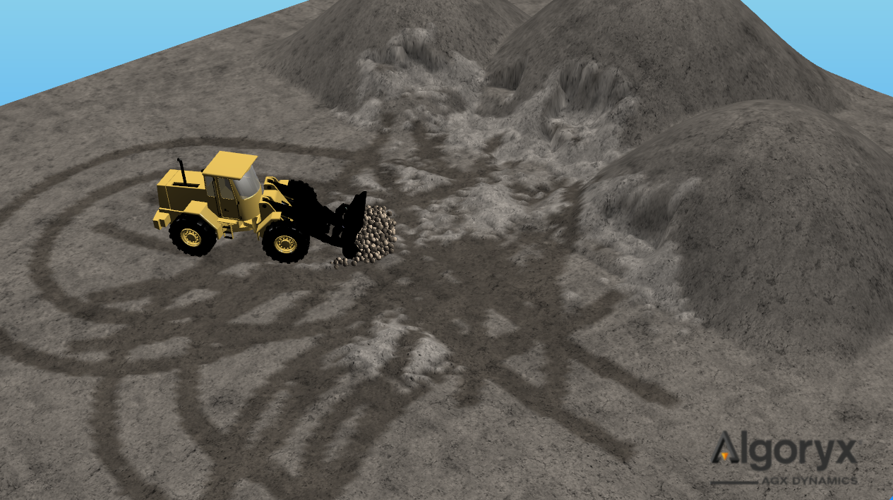
Fig. 23.11 Figure showing a wheel loader scene during excavation that illustrates terrain soils of different compaction levels through
lightness rendering. Dark surface patches in the soil shows wheel tracks from compressed soil with a compaction level higher
than the nominal compaction. The lighter areas show soils of looser compaction resulting from excavation or avalanching where
it grows in volume according to the swell factor of the material. Soil of loose compaction offers less resistance and is
easier to compress.
Default compaction for an initialized terrain is 1.0 in all terrain grid elements. Compaction can be set for all grid cells via the following function:
/**
Set a compaction for all current active solid grid elements in the Terrain object.
\note - the terrain grid elements all start with a the nominal compaction value of 1.0, of which all
user specified bulk parameters correspond to.
\param compaction - The compaction value to set to every voxel in the terrain (Default: 1.0)
\param replaceCompactedSoil - True if all voxels which already have a compaction value (compaction != 1.0)
                              should get overwritten.
*/
void setCompaction(agx::Real compaction, bool replaceCompactedSoil=true) const;
The TerrainGridControl class can be used to access and set the compaction value for single grid cells at the surface or at a 3D grid index.
float TerrainGridControl::getCompaction(const agx::Vec2i& terrainIndex, int z) const;
float TerrainGridControl::getSurfaceCompaction(const agx::Vec2i& terrainIndex) const;
void TerrainGridControl::setCompaction(const agx::Vec3i& terrainIndex, float compaction, bool compressOccupancy = false);
void TerrainGridControl::setSurfaceCompaction(const agx::Vec2i& terrainIndex, float compaction, bool compressOccupancy = false, bool compressToBottom = false);
Compaction can also be set from the surface to a specified depth:
void TerrainGridControl::setSurfaceCompactionToDepth(const agx::Vec2i& terrainIndex, float compaction, float depth);
The soil is normally compacted via contacts from external geometries that generates surface terrain contacts where the contact area is calculated from the voxels that the geometry is overlapping. A uniform surface stress in the voxel contact patch is estimated from the contact force and the estimated area. The active terrain contacts that generate soil pressure can be extracted from the terrain and it’s properties extracted:
auto terrainContacts = terrain->getTerrainContacts();
for( const auto& c : terrainContacts )
{
  auto geometry           = c.getGeometry();
  agx::Real surfaceStress = c.getSurfaceStress();
  agx::Real area          = c.getArea();
}
Pressure propagates down into the soil by approximating the surface in each voxel as a uniform plate. The pressure thus decays according to the formula:
where \(\sigma^{v}_{z}(z)\) is the local stress in depth \(z\) from the surface, \(A_s\) is the plate area and \(\sigma_s\) is the uniform surface stress.
The soil is compacted in a grid cell if it exceeds the local preconsolidation stress from earlier compactions
or the starting preconsolidation stress. The level of compaction is determined by the specified compression index
and the preconsolidation stress in the Compaction Properties. The compression index is defined as a logarithmic
dependence between the change in compaction/void ratio from stress:
The new density in a grid cell is thus calculated via the following expression:
where the \({\phi}_0\) is the volume fraction of the material, \(\sigma_0\) the preconsolidation stress of the material, \(C_c\) the compression index of the material, \(\sigma\) the local stress and \(\rho_0\) the density if the material at compaction 1.0 (i.e the bank state).
This is then used to calculate the compaction level at grid cell \(i\):
One can apply a time relaxation to the rate of compaction changes in the terrain. It is governed by the following equation:
where \(\tau\) is the time relaxation constant and \(t_c\) is the contact duration time. The timefactor is multiplied with the estimated density changes and approaches 1.0 as the contact time increases.
The parameters for the soil compaction algorithms can be found and adjusted in the CompactionProperties object.
23.18.1. Material changes from compaction
Some material properties change locally from compaction level.
23.18.1.1. Young’s Modulus
The local Young’s Modulus in a grid element changes according to the following relation:
where \(E_0\) is the bulk elasticity in the bank state and \(k_e\) and \(n_e\) are hardening parameters that have default values of 1.0 and 0.5 respectively.
23.18.1.2. Dilatancy Angle
The level of compaction of the soil affects its dilatancy angle which in turn affects the internal friction of the material. The effective internal friction angle of the material thus becomes:
Where \(\phi_{eff}\) is the effective friction angle, \(\phi\) the base internal friction angle of the material and \(\psi_{dilatancy}\) is the dilatancy angle of the material. The effective internal friction angle of the soil is used to determine the soil wedge failure shapes and the resulting friction coefficient of the terrain <-> aggregate contacts. The dilatancy angle is given by:
Where \(\varphi\) is the local compaction and \(\varphi_c\) is the critical compaction, at which the soil switches between expanding or shrinking during shearing and \(c_{psi}\) is a constant that depends on particle shape.
Note
Note that the dilatancy angle of the material does not affect angle of repose. This has a separate compaction effect and is also affected by the delta repose of the material.
23.18.1.3. Swelling
When solid soil undergoes transformation to dynamic soil during excavation, the soil particle bulk volume expands according
to the specified Swell Factor of the material. When the dynamic soil is transformed back to solid during merge it will
have a compaction level according to:
where \(c_i\) is the local compaction at grid element i and \(S_f\) is the Swell Factor.
23.18.1.4. Angle of Repose
The local angle of repose changes with varying compaction levels by adjusting the allowed relative heights between two grid elements by using the following formulation:
where \(M\) is a constant, \(\psi_{r}\) is the effective repose angle of the material, \(L\) is the length of a grid cell, \(c_i\) is the local compaction level at cell i. This effectively means that compaction levels above 1.0 increases the angle of repose for the material.
23.19. Dynamic Soil
Dynamic mass is created in the active zone intersection between the Shovel and the Terrain. It consists of both fluid mass and soil particles.
Soil particles are expressed in the form of 6-degrees of freedom (6-DOF) soil particles with hertzian contact dynamics, Coulomb friction and rolling resistance. The user can access and create soil particles via the soil simulation interface. The soil particles created from the shovel active zone intersection is simulated in the main simulation and can interact with other objects. By default, only the particles see the shovels as kinematic objects. This means that the particles themselves do not give force feedback to the shovels. The mass in the active zone, from both dynamic and solid mass, is used in the construction of the active zone aggregate that generates force feedback on the shovel through created contacts.
Note
The number of active soil particles depends on the amount of grid points touched by the dig volume which is a function of both blade size, dig depth, terrain resolution and dig length. A larger volume of influence means increased numbers of touched grid points and created particles which leads to an increase in computational time.
Soil particles are created when the active zone of the shovel touches new grid points. Fluid mass is generated if the shovel continues to remove mass from the same grid point and is then spread onto existing particles in the area, increasing their size. The fluid mass movement is integrated using a velocity field in the terrain grid generated from the shovels and the soil particles. If there are no particles that the fluid can merge to, it will merge back to the terrain.
Particles are also resized locally to cluster around a nominal radius. This is calculated from the resulting element size upon
construction of the terrain object. It is also modified by the material swell factor and estimated packing ratio of the particles so that
the total bulk volume of the particles created should correspond to the volume excavated, modified by the expected volume swelling. This radius can
be extracted by using the following function:
agx::Real getParticleNominalRadius()
The radius that the particles cluster around can be altered using the soil particle scaling factor. What this does is that it alters the
average radius of the soil particles, this can be used either to reduce the number of particles in the simulation to gain a potentially significant
performance increase, or by increasing the number of soil particles to increase fidelity or better dynamic soil visuals. This scaling factor can be
set and extracted using the following functions respectively:
void getProperties()->setSoilParticleSizeScaling( 1.5 )
agx::Real getProperties()->getSoilParticleSizeScaling()
The contact network between the soil particles is solved using an iterative Parallel-Projected-Gauss-Seidel Solver (PPGS) together with the rest
of the system. It is enabled in the simulation as soon as a terrain instance is added. The user can also set the fidelity of the solver by adjusting
the setNumPPGSRestingIterations which sets the number of iterations used in the PPGS solver. Increasing the iteration number typically results
in the better solution and may be necessary when the particle counts increases in the simulation in order to get correct bulk behavior with stable
particle piles that merge properly with the terrain. The default number is 25 iterations:
simulation->getSolver()->setNumPPGSRestingIterations( 25 );
simulation->getSolver()->setUseParallelPgs( false );
Warning
The PPGS solver currently disables island partitioning which means that performance will be lost if the scene contains multiple self-contained systems.
23.19.1. SoilSimulationInterface
Users can extract the agxTerrain::SoilSimulationInterface to access and create soil particle data
in the terrain. The currently active dynamic soil particles in a simulation can be accessed via the
following function:
auto soilSimulationInterface = terrain->getSoilSimulationInterface();
agx::Real totalMass{ 0.0 };
agx::Real averageRadius{ 0.0 };
auto soilParticles = soilSimulationInterface->getSoilParticles();
for ( auto& particle : soilParticles )
{
  totalMass += particle->getMass();
  averageRadius += particle->getRadius();
  agx::Vec3 position = particle->getPosition();
  agx::Vec3 velocity = particle->getVelocity();
}
averageRadius /= soilParticles.size();
Note
Do note that changing either mass, material or radius will change the mass of the particle and thus violate mass conservation.
Warning
It is not recommended to change particle properties such as mass and material as those are derived from the Terrain instance.
Individual soil particles can be created and removed manually:
auto soilSimulationInterface = terrain->getSoilSimulationInterface();
agx::Real radius = terrain->getParticleNominalRadius();
agx::Vec3 position{ 0.0, 0.0, 1.0 };
agx::Vec3 velocity{ 0.0, 0.0, 0.0 };
auto soilParticle = soilSimulationInterface->createSoilParticle(radius, position, velocity);
soilParticle->setPosition( ... );
soilParticle->setVelocity( ... );
...
soilSimulationInterface->removeSoilParticle( soilParticle );
Before doing any operations on the particles in the terrain, it can be useful to check if the particle is valid or not already removed:
auto soilParticles = soilSimulationInterface->getSoilParticles();
for ( auto& particle : soilParticles )
{
  if ( soilSimulationInterface.isValid( p )
  {
    ...
  }
}
Soil particle collisions can be controlled via the collision group system in agxCollide::Space and
added to the created soil particles via the soil interface:
// Create a collision group and add it to all particles
agx::Name collisionGroup { "myCollisionGroup" };
soilSimulationInterface->addCollisionGroup( collisionGroup );

/**
Disable collisions between the objects that have the specified group. This will prevent particles
from colliding with each other.
*/
simulation->getSpace()->setEnablePair( collisionGroup, collisionGroup, false );
The current active bulk volume of soil particles can be extracted by using the following function:
/**
\return soil particle bulk volume (m3) active in the simulation.
\note - the bulk volume is the specific volume of all particles divided with the
        estimated particle packing fraction (0.67)
*/
agx::Real calculateSoilParticleBulkVolume() const;
The internal GranularBodySystem used for simulating the soil particles can be extracted and used with other objects, such as a
agx::ParticleEmittter to create masses of soil particles.
agx::Physics::GranularBodySystem* getGranularBodySystem() const;
Warning
When using an emitter with the GranularBodySystem, the emitter particle material should be the same as the particle material of the terrain that the emitted particles should belong to! The particle material is used by different terrains in the simulation to determine which particle belongs to which terrain instance.
23.19.2. Custom soil failure volume
In certain cases it is desirable to be able to trigger soil conversion into dynamic soil particles manually without the terrain interacting with a shovel. This can be achieved by creating a soil failure volume and providing it to the terrain. The following code showcases how to trigger soil failure in a 1x1x1 box:
agxCollide::Box failureVolume = agxCollide::Box(0.5,0.5,0.5);
terrain->convertToDynamicMassInShape(failureVolume);
23.20. Excavation Model
We refer to the published academic paper 1 for a more in-depth explanation of the mathematical model for agxTerrain. This section will only provide a brief overview of the different components of the model.
During setup of a shovel, deformation planes are created from the geometry of the shovel. As the shovel interacts with the terrain, active zones are generated in the deformation planes. The active zones consists of discretized soil wedges that are created from soil mechanics theory.
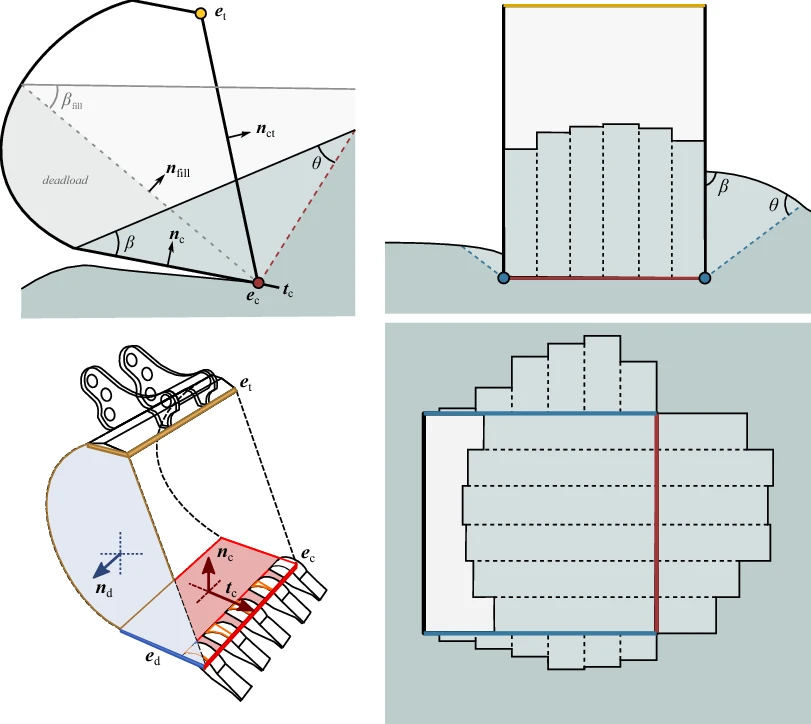
Fig. 23.12 The left images illustrate a digging tool with a cutting edge e c (red line), separating plate n c (red face), deformer edge e d (blue line), deformer face n d (blue face) and top edge e t (yellow line). The inner shape is indicated with the dashed lines. The normal n fill of the secondary separation plate range from n c to n ct depending on the fill ratio of the inner shape. The three active zones, discretized by vertical wedges, is illustrated from the rear (upper right) and from above (lower right).
Four different excavation planes are automatically constructed from the shovel edges, each corresponding to a mode of deformation:
Primary |
This is the primary excavation mode of the shovel that is driven by the |
Deformer Back |
This is the deformer plane defined by the underside of the shovel. Used in grading and push operations. |
Deformer Left |
This is the deformer plane to the left side of the shovel. Used in grading and push operations. |
Deformer Right |
This is the deformer plane to the right side of the shovel. Used in grading and push operations. |
These individual planes can be configured.
23.20.1. Mass deformation model
As the shovel moves through the terrain it converts solid mass into dynamic mass in the active zone, consisting and internal fluid and particle mass:
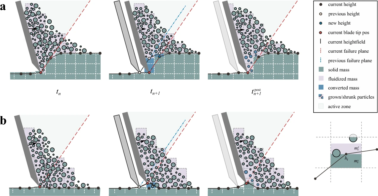
Fig. 23.13 As a blade and its active zone moves into the terrain a, new solid voxels are resolved into particles or fluidized mass that form the aggregate body. The voxel height value, corresponding to the solid occupancy, is found by projection to the failure plane of the active zone. When the blade is raised b, the gap is filled by solid mass converted from fluidized or particle mass in the vicinity of the edge.
23.20.2. Excavation Resistance Model
Force feedback in the separation and deformation mode is generated by aggregate rigid bodies created from dynamic and solid
mass in the shovel active zones. Contacts are created both between the shovel and the aggregate and the aggregate and terrain. The
resulting forces depend on the contact materials properties derived from the agxTerrain::TerrainMaterial
bulk properties and also the contact material between the shovel and the terrain
that is used for the shovel-aggregate contacts.
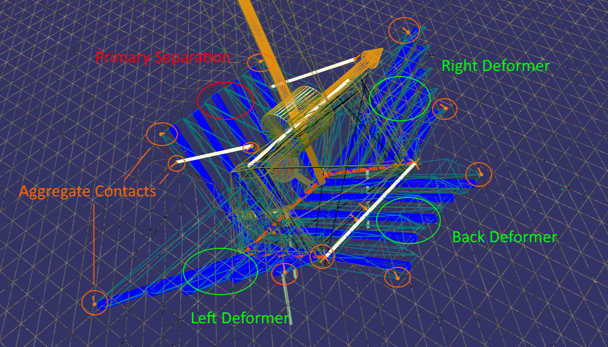
Fig. 23.14 Figure showing the aggregate formation during excavation. Primary separation resistance is denoted in red and the deformer zones are denoted in green. The resulting aggregate contacts for aggregate <-> terrain and aggregate <-> shovel are denoted in orange. The blue lines denote the direction of the soil wedges that are created in the terrain via calculation using the Fundamental Earth Moving model (FFE) and the material bulk properties. These soil wedge shapes are the basis for the failure zone that ultimately form the soil aggregates in the separation and deformer zones.
23.20.3. Penetration Resistance Model
Pure penetration occur when a thin tool moves straight into the terrain, displacing only the soil necessary for fitting the tool. Buckets are often penetrated deep into the soil before separation (cutting) starts. The penetration resistance experienced by a tool consists of two main parts: from the teeth (or edge) and from the primary separating plate. The resistance from the separating plate contacting the soil is simply modeled by a frictional force proportional to the passive earth pressure in the soil. The pressure on the teeth during penetration can be modeled by using the cavity expansion model. The penetration force acts in the cutting direction of the Shovel.
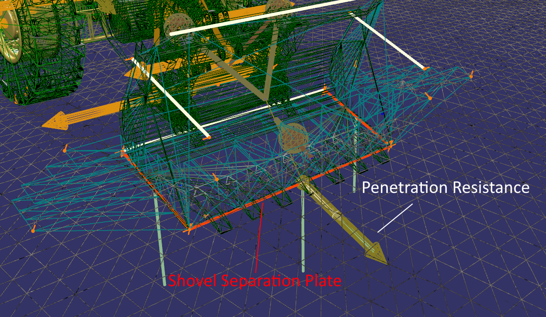
Fig. 23.15 Figure illustrating the shovel <-> terrain interaction during a wheel loader digging process. The penetration resistance works in the cutting direction parallel to the separation plate of the bucket and is expressed as a prismatic velocity constraint with force limits according to the penetration model theory.
23.21. Performance notes
The performance of agxTerrain depends on the number of dynamic soil particles in the simulation. The number of active soil particles depends on the amount of grid points touched by the dig volume, which in turn is a function of both blade size, dig depth, terrain resolution and dig length. A larger volume of influence means increased numbers of grid points and more particles, and thus an increase in computational time.
The number of solver iterations set via setSolverIterations via SoilSimulationInterface also determines the overall performance. Increasing the
solver iterations is needed when particle count increases in order to get stable soil piles. A low iterations count relative to the amount of particles
will results in an error that introduces numerical vibrational noise in the contact forces, causing the particle piles to “melt”. A typical cue of when
to increase solver iterations is when the particles are unable to merge with the terrain due to this numerical noise.
Do note that the material parametrization of the terrain, with the exception of terrain resolutions, does not overtly affect the performance. This means that soil behavior should be achieved without compromising performance.
References
23.22. FAQ
23.22.1. Questions
23.22.2. Answers
Why do I get an error of “bad soil wedges” during excavation?
This error occurs when the soil wedge geometries are improperly constructed, due to a faulty shovel setup. The problem is typically associated with misaligned vectors, specifically in the top edge or cutting edge directions. To resolve the error, consider adjusting the orientations of these vectors to ensure proper alignment.
Why is my shovel not digging?
There are several reasons why your shovel might not be digging. First, take a look at the Shovel setup section here in the User Manual.
The vectors specified in the schematic can be seen in debug mode, which is accessed by pressing g in agxViewer.
If that does not help, try to resolve the following questions:
Is the cutting direction vector specified in the correct direction?
Is the cutting edge vector actually aligned with the shovel geometry?
Is the shovel added to the terrain you want it to dig in?
Is the terrain added to the simulation?
There are also several tutorials where shovels are setup from simpler geometric shapes in the data\python\tutorials\agxTerrain folder.
How can I reduce the amount of soil particles in the simulation without lowering the terrain resolution?
The amount of particles in the simulation can be adjusted with the following method:
auto* properties = terrain->getProperties();
// Increase the particle radius by a factor of two.
properties->setSoilParticleSizeScaling(2.0);
This scaling factor modifies the nominal radius of the created soil particles with a scalar factor. Increasing the nominal radius will adjust the soil mass resizing algorithm to increase the particle size and correspondingly reduce the amount of particles in the simulation.
How can I modify the digging resistance?
The digging resistance encountered during excavation is a combination of several forces. The primary approach for modifying digging resistance includes fine-tuning the contact material properties between the shovel and terrain. This affects both penetration, separation and deformation resistance. Additionally, tweaking the terrain material properties, such as soil density and friction angle, can change contact forces between aggregate and terrain.
The effective terrain material properties used in the force calculations are also affected by the local compaction in the terrain, which also can be adjusted manually. There is also a PenetrationForceScaling parameter which can be used to adjust the penetration resistance.
The User Manual provides a dedicated chapter on the Calibration of excavation resistance, and there is also a chapter on soil compaction, which we urge you to read in case you are interested in modifying the digging resistance.
How do I measure the amount of material in a bucket?
One way to do this is to measure the total weight of the soil aggregates in the shovel.
There are two kinds of aggregates that are created:
Inner body = the inner body inside the confines of the shovel.
Wedge bodies = the soil wedge bodies that are created during excavation.
To get the amount of material inside the confines of the bucket, use the following method:
agx::Real innerBodyMass = shovel->getSoilParticleAggregate()->getMass();
To get the amount of material in the wedge bodies, use the following method:
agx::Real wedgeBodyMass = shovel->getSoilParticleAggregate()->getTotalAggregateMass() - innerBodyMass;
Of course, you can use the following method to get the combined mass for all aggregates formed in and on the shovel.
shovel->getSoilParticleAggregate()->getTotalAggregateMass();
How can I calculate the amount of transported/excavated material?
This is quite complicated to achieve but possible. During each dig cycle, a moment where the shovel contains the amount that is excavated/transported needs to be identified.
Preferably this is while the shovel is raised above the ground. In that moment we measure the amount of material in the bucket, and then we dump the contents of the shovel somewhere. The amount measured during the repeated dig cycles then needs to be summed up in the end, to find out how much material has been transported/excavated during the simulation.
Note that there is a method on the terrain which can be called in every POST-step to get the last excavated volume in [m^3]:
agx::Real lastExcavatedVolume = terrain->getLastExcavatedVolume();
This is the volume which is transformed into dynamic mass in each timestep and not that which is captured by the shovel.
How can I use the terrain on the bed of a truck?
This is achieved by adding the terrain geometry to the truck’s rigid body:
// Given that truck is an agx::RigidBody
truck->add(bedTerrain->getGeometry());
The bedTerrain must be constructed to fit onto the bed of the truck. To allow tipping, failure zones also have to be constructed which trigger the
conversion of the solid terrain into dynamic mass when the bed is tipped to a certain angle. How this is done is shown in the tutorial tutorial_soil_failure_volume.agxPy.
How can I simulate mud so that I sink down with the vehicle?
You can simulate the sinking into the terrain by using soil compaction. How much the vehicle sinks is defined by the terrain materials compaction properties, which are accessed via the following method:
auto compactionProperties = terrainMaterial->getCompactionProperties()
Where the terrain material is in the desired area.
The tutorial tutorial_compressed_soil.agxPy shows some basics of manipulating the compaction properties of a terrain material to allow sinkage of external objects.
How can I “reset” the terrain quickly to its initial state?
For a single terrain, this can be achieved by saving the terrain heights in the initial state and then later setting the heights again. Use the following methods:
agx::RealVector initialHeights = terrain->getResizedHeightField(1, 1);
//... later in the simulation, use the initialHeights to reset the height field:
terrain->setHeights(initialHeights);
The setHeights method also takes a resetCompaction parameter, which by default resets the compaction values in the terrain.
This means if you have changed the compaction values manually with the terrain->setCompaction(agx::Real compaction) call, this needs to be repeated.
Similarly, if you have added any additional terrain material configurations, the information of which terrain
material existed in the excavated terrain may have been lost and need to be reapplied again.
Also, if you have performed some sort of excavation operation you might also need to remove lingering particles. This can be achieved via the granular system:
auto soilParticles = terrain->getSoilSimulationInterface()->getSoilParticles();
for(auto sp : soilParticles)
  terrain->getSoilSimulationInterface()->removeSoilParticle(sp);
For a paged terrain, when using a TerrainPager, resetting can be achieved by calling the terrainPager->reset() method.
This method will reset all terrain tiles to their initial states, as set by the TerrainDataSource, including the currently active tiles.
How do I adjust the static angle of repose in my simulations?
The angle of repose is controlled via the following terrain material parameters:
// The friction angle(radians) has 1:1 relationship with the angle of repose of the material
bulkProperties->setFrictionAngle(0.7);

// The delta repose angle (radians) that is applied on the friction angle when determining the angle of repose of a material.
bulkProperties->setDeltaReposeAngle(0.15);
You can adjust these to get the angle of repose you want. It is also worth noting that soil compaction also modifies the local angle of repose.
How can I simulate dry or wet sand?
You can simulate both dry and wet sand by adjusting specific terrain material parameters. Two key parameters to focus on are bulk density and bulk cohesion, and the internal friction angle plays a role as well. Dry sand typically has a lower bulk density than wet sand, reflecting the absence of added moisture. On the other hand, simulating wet sand involves increasing the bulk density, as water contributes to the overall mass.
In granular materials with particles exceeding 0.1 mm in diameter, repulsive forces usually dominate. However, as moisture content rises, bulk cohesion may increase due to capillary forces and chemical reactions at particle contact points. It’s important to note that excessive water content can lead to pore pressure, diminishing attractive contact forces and thereby reducing internal friction, a parameter influenced by the internal friction angle. Consequently, bulk cohesion may decrease as capillary forces diminish.
In summary, manipulating the terrain material properties of bulk density, bulk cohesion, and the internal friction angle allows for the accurate simulation of both dry and wet sand conditions.