18. AGX PowerLine
In AGX Dynamics, a power line represents a collection of connected components that transport power across a system, typically from some kind of source to a set of consumers. Examples of power lines are a drive train moving torque from an engine to the wheels of a car or a truck, or a hydraulic circuit converting pressure from a pump into linear motion of a hydraulic cylinder.
Despite the name the structure of a power line does not need to be a simple line, but arbitrary graphs are supported. Using converter components, it is also possible to mix hydraulic and drivetrain components in the same power line. While the agxPowerLine namespace contains some basic components, most of the functionality is provided by the agxDriveTrain and agxHydraulics namespaces.
Using the AGX PowerLine library it is possible to share a power source among several consumers and thereby include the various system failures that can occur due to insufficient available power in the simulation.
18.1. Design philosophy
The most basic building blocks of the AGX power line are the one-dimensional bodies that represent the motion within each of the constituent components. For a drivetrain the motion is the rotation of the various shafts and gears, and for a hydraulic system it is the motion of fluid through pipes and valves. The toolkit can also represent linear motion. We call these the three dimension types. The one-dimensional bodies are connected together when the power line components are connected, which causes motion in one body to affect the neighboring bodies. The power line itself imposes no limitation in how components are connected, arbitrary graphs are allowed, but particular hydraulic or drivetrain components may limit how that particular component may be connected to other components.
Every component has an input and an output side. The sides may differ both in the number of connections that the side allows, and the type of dimension that it may connect to. The sides at which two components are connected define the direction of motion where output-to-input is the default and corresponds to positive-to-positive motion. Connecting output-to-output or input-to-input causes the two components to move in opposite local directions.
The power propagation can cross between the one-dimensional power line world and the six-dimensional mechanical world at specified transition points. A transition point is a pair consisting of an AGX constraint such as a hinge or a prismatic and a type of power line component called an Actuator.
The various components that make up a power line are owned by a particular PowerLine instance, which in turn is owned by the Simulation. To simulate a power line one first creates the PowerLine object and a collection of components. The components are added to the PowerLine and connected together, while the PowerLine is added to the Simulation.
18.2. Component types
The components that take part in a power line in AGX Dynamice are of one of two types: Unit or Connector. Every class representing a drivetrain or hydraulic component inherit from one of these two classes, either directly or indirectly. The two types are fundamentally different internally, but are used in similar ways. The create-add-connect pattern applies to both, but see the section titled “Connecting components” for more details.
18.2.1. Unit
A Unit holds the one-dimensional bodies that represents motion within the power line. The bodies are actually owned by instances of subclasses of the PhysicalDimension class; either RotationalDimension, TranslationalDimension or FlowDimension depending on which dimension type the Unit contains. The PhysicalDimension exposes the rotational-, translational or flow velocities in the component in a uniform, one-dimensional way. This is called the gradient of the PhysicalDimension. A PhysicalDimension also has a mass property that relates the load type of the dimension, e.g., force, torque or pressure, to acceleration within the Unit. The mass property is simply the mass or inertia in the case of translational and rotational dimensions, respectively, but more complicated for a hydraulic dimension.
The Unit defines connection points into the Unit. A connection point is a PhysicalDimension that other components may connect to. A Unit may have multiple connection points and may return a different PhysicalDimension instance depending on whether the connection concerns the input or output side.
18.2.2. Connector
A Connector represents transfer of power between Units. Whenever two or more Units are connected a Connector is used to link them together. It does this by creating a constraint between the bodies held by the PhysicalDimensions in the connected Units. The specifics of the constraint define the operation of the Connector and the Connector may provide configuration options that are used to control the constraint parameters. The configuration options may have been given component-specific names in order to be more domain oriented.
A Connector does not generally have any PhysicalDimensions of its own.
Much like the Unit, the Connector defines connection points for its inputs and outputs. The Connector specifies which type of dimension may be connected to each of the two sides. A connection between a Connector and a Unit can only be made if there are matching connection points for the sides being connected. More on making connections in the section titled “Connecting components”.
18.2.3. Composite components
Some components are more complicated than what a regular Unit or Connector can represent. In such cases the toolkit provides composite components, which are Units and Connectors that contains other components. All components have a primary type, so even if a composite component may contain both Units and Connectors, the component itself is always either a Unit or a Connector and can be used as-if it was a regular Unit or Connector.
A composite Unit may be empty in the sense that it doesn’t contain any PhysicalDimensions of its own. Instead it contains internal Units that provide them. When asked for its connection point the Unit will return one of the PhysicalDimensions of the internal Units. A similar pattern may be used for Connectors and constraints.
Composite components commonly provide accessor methods for the internal components. Care should be taken when manipulating such components so that any invariants maintained by the composite component isn’t broken. In general, connect calls involving internal components are advised against, unless explicitly suggested by the composite component’s documentation.
18.2.4. Actuator
An Actuator is a type of Unit that forms a bridge between the one-dimensional power line and the six-dimensional mechanical world within the simulation. Examples of actuators are wheel axles on a vehicle and hydraulic cylinders on an articulated arm. Whenever there is motion within the power line there will be a corresponding motion in the mechanical system, and vice versa. There are two basic forms of Actuators: RotationalActuator and TranslationalActuator. There are also variants of these, such as PistonActuator that is a TranslationalActuator transforming hydraulic pressure and flow into translational motion.
Actuators are always created from a regular AGX constraint and for a 1-DOF constraint the effect of the power line onto the bodies is by default the same as-if the Motor1D of the constraint had been used. Creating a RotationalActuator for a hinge will cause rotation about the hinge’s axis and a TranslationalActuator associated with a prismatic will cause translational motion along the prismatic’s axis. The coupling is two-way, so the power source in the power line will feel the load from the mechanical bodies, including forces from other constraints, contacts and external forces such as gravity.
Constraints with a more complicated geometry than Constraint1DOF will need to provide additional information in order to connect to an Actuator.
This information is supplied in the form of a ConstraintGeometry instance, which describe the location and direction on the rigid bodies at which the Actuator should act.
An example of a such a constraint is the WheelJoint, which provide the corresponding WheelJointConstraintGeometry which makes it possible to attach an Actuator to either the wheel, steering, or suspension axes of a WheelJoint.
18.2.5. Connecting components
Components are connected using the various connect methods. The most basic form:
component1->connect(component2);
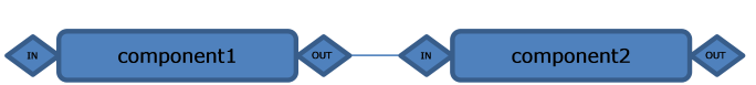
connects the output side of component1 to the input side of component2. The general rule is that a connect call must contain both a Unit and a Connector, but for the simplest cases the Connector can be created implicitly. The system may also chose to reuse a Connector that is already present at one of the connection points. This make it possible to connect two Units directly.
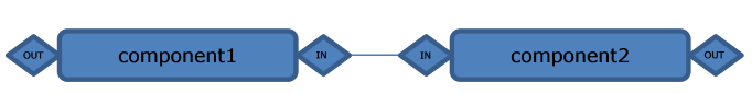
To create more complicated power lines it becomes necessary to specify on which side of a component that a connection should be made. This is done by passing side flags to the connect methods. The following example connects the input side of component1 to the input side of component2.
component1->connect(INPUT, INPUT, component2);
Units contain PhysicalDimensions of various types and the Connectors declare, for each side, which type or types of PhysicalDimensions the Connector can connect to. For a connection to be successful there must be at least one match between the dimension types that the Connector expects and the types that the Unit provides. Connectors can also have a maximum number of allowed connections for each side. Attempting to connect a Unit to a Connector that has reached the maximum number of connections at the given side will fail.
Units have a notion of forward, or positive, motion. It is defined as the direction moved when the value of the Unit’s PhysicalDimension is positive. The normal case has two connection possibilities. Connecting two Units at different sides, i.e., output-to-input or input-to-output, causes the direction to be maintained, and connecting two Units at the same side, i.e., output-to-output or input-to-input, causes the motion to be reversed. Some Connectors, such as a gear box with a reverse gear in, can change this behavior.
18.2.6. Direct body manipulation
Since the PhysicalDimensions are one-dimensional it is possible to pack multiple dimensions into the same agx::RigidBody, which is done for performance reasons. A consequence of this is that care must be taken when manipulating the body since any change may influence other Units in unexpected ways. To avoid this issue for individual PhysicalDimensions it is possible to reserve the body for that PhysicalDimension only. This is done by calling PhysicalDimension::reserveBody. The body is then accessed by calling PhysicalDimension::getOrReserveBody.
In order to meaningfully manipulate a reserved power line body it is necessary to know its direction. For a rotational dimension the direction is the axis around which it rotates, and for translational and flow dimension it is the direction of motion. The world direction is provided by PhysicalDimension::getWorldDirection. The direction should always be fetched after the body has been reserved because the reserve process may change the world direction. The direction should be taken into account when, for example, attaching a constraint to the reserved power line body. The constraint creation helper function agx::Constraint::createFromWorld can help with this.
The following code snipped demonstrates how to drive a shaft using the motor on a regular hinge.
agxDriveTrain::ShaftRef shaft = new agxDriveTrain::Shaft();
agxPowerLine::RotationalDimension* rotDim = shaft->getRotationalDimension();

agx::RigidBody* body = rotDim->getOrReserveBody();
agx::HingeRef hinge = agx::Constraint::createFromWorld<agx::Hinge>(
    body->getCmPosition(), rotDim->getWorldDirection(), body);
simulation->add(hinge);
hinge->getMotor1D()->setSpeed(agx::Real(2.0));
hinge->getMotor1D()->setEnable(true);
hinge->getMotor1D()->setForceRange(agx::RangeReal(agx::Real(100000.0)));
18.3. Rotational and Linear Actuators
By using the RotationalTranslationalHolonomicConnector class it is possible to connect rotational constraints to linear and vice versa.
Fig. 18.1 illustrates a system where a hinge is used to power a prismatic constraint. A rotation of the hinge will lead to a linear motion in the prismatic.
For more illustrative examples, see data/python/linear_actuator.agxPy and data/python/torque_drive_winch.agxPy
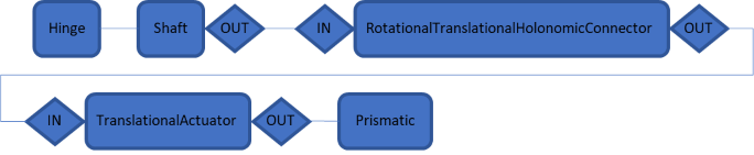
Fig. 18.1 A prismatic powered using a hinge through a drivetrain system.
// Build a drivetrain that connects a hinge to a prismatic constraint
agxDriveTrain::ShaftRef shaft = new agxDriveTrain::Shaft();
agxPowerLine::RotationalDimension* rotDim = shaft->getRotationalDimension();

agx::RigidBody* body = rotDim->getOrReserveBody();
agx::HingeRef hinge = agx::Constraint::createFromWorld<agx::Hinge>(
    body->getCmPosition(), rotDim->getWorldDirection(), body);
simulation->add(hinge);
hinge->getMotor1D()->setEnable(true);
hinge->getMotor1D()->setSpeed(0.5);

// Connect the prismatic constraint to the drivetrain using a TranslationalActuator
auto linearActuator = new agxPowerLine::TranslationalActuator(prismaticConstraint);
auto connector = new agxPowerLine::RotationalTranslationalHolonomicConnector();

shaft->connect(connector);
socket->connect(linearActuator);