15. AGX Wire
The agxWire module contains numerous classes for simulating wires, ropes and chains. These classes can be used to simulate cranes, winches, pulleys etc. The wire is an implementation of a lumped element structure with dynamic resolution. The main difference between classical lumped elements, such as chains of bodies and ball socket joints (or hinges), is that the wire will adapt the resolution so that no unwanted vibrations will occur. Whenever a wire slides over a geometry (such as a box, cylinder or trimesh), it will create shape contact nodes, which will stabilize contacts even under very high tension. The Wire is stable even under very high mass ratios/tension. This is necessary to be able to model real life scenarios with wires, chains, ropes etc.
Wire-wire interaction can also be enabled (not enabled by default). The overlap test between wire-wire is performed with sweep tests (continuous collision detection) to reduce the risk for accidental missed overlaps.
15.1. Known limitations
The current limitations of the wire are:
A wire cannot handle torsion. However, rotation for Link’s between Wire’s can be controlled. See Section 15.21.6
15.2. agxWire::Wire
agxWire::Wire (wire) has one material for the whole wire. Available operations on a wire are: cut, reverse, merge. It can be winched using the class agxWire::WireWinchController.
Below is a table of classes in the agxWire namespace.
15.3. Modeling primitives
CLASS |
Description |
|---|---|
agxWire::Wire |
Class for simulating a wire of a single segment type. |
agxWire::WireWinchController |
A winch that can spool in/out wire |
agxWire::WireSimpleDrumController |
A drum implementation for use with the agxWire::Wire class. |
15.4. Wire nodes
CLASS |
DESCRIPTION |
|---|---|
agxWire::Node |
Base class for a node used when routing an agxWire::Wire. A wire is forced to pass through this specified point. |
agxWire::FreeNode |
Nodes used for routing a wire at points in the world coordinate system. |
agxWire::BodyFixedNode |
Nodes used at end of wires to attach rigid bodies. |
agxWire::EyeNode |
A node which defines a “hole” through which the wire can slide. A Link can not slide through an EyeNode. |
agxWire::ContactNode |
OBSOLETE! A node which is either created by the user, or by the collision detection system to any edge where the line is overlapping geometries. Can only exist on geometries with single shapes. The shape can only be box, cylinder or some type of mesh. |
agxWire::ShapeContactNode |
A node which is either created by the user, or by the collision detection system to any edge where the line is overlapping geometries. No limitation on on the number of shapes for a geometry. Can exist on all shapes, expect lines, rays and WireShapes. |
agxWire::ConnectingNode |
A node commonly used to attach a rigid body between two agxWire::Wire. This node has additional stabilization constraints. |
15.5. Rendering a wire
CLASS |
DESCRIPTION |
|---|---|
agxOSG::WireRenderer |
Class for rendering an agxWire::Wire in OpenSceneGraph |
agxWire::NodeConstIterator |
Iterator for accessing nodes in a Wire. |
15.6. Overall description of a Wire
15.6.1. Dynamic Resolution
A wire’s route is defined by its nodes. There are various nodes for different purposes. Nodes are explained later in the document.
A very important concept of a Wire is the ability to change resolution of nodes per length unit. A Wire with a certain material (radius/density) will have a certain mass. If this mass is distributed along the wire in many nodes (lumped elements), we will get small masses in each node. If a Wire with many small masses is affected by a large tension, we will get oscillations due to the large ration between tension and mass of each mass element. Therefore, the Wire will automatically remove nodes during high tension.
The maximum resolution for a Wire is specified in its constructor
agx::Real resolution = 2; // Two lumped elements per meter is the max resolution.
agxWire::WireRef wire = new agxWire::Wire(
                       0.01,         // Radius
                       resolution ); // Number of elements per length unit
or through the call:
void agxWire::setResolutionPerUnitLength( agx::Real resolutionPerUnitLength );
15.6.2. Constraint model of a Wire
A wire consists of a set of bodies and constraints. From the attributes in the agxWire::Wire class, a structure is created which contain the physical model of a wire.
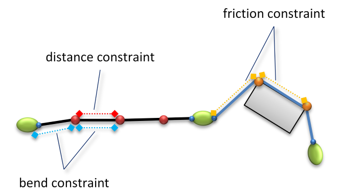
Fig. 15.1 The various constraints involved in the modeling of a Wire.
Fig. 15.1 illustrates the schematic structure of a simulated Wire. The constraints involved are:
Constraint model |
Description |
|---|---|
Distance constraint |
A distance constraint will try to keep the two bodies locked at a specified distance. There are distance constraints between all nodes (bodies) in a wire. |
Bend constraint |
A bend constraint is a three body constraint that will try to restore the wire into a straight line. A Wire with a large radius is of course much more resistant against bending than a thin rope. A bend constraint also increases stability for a Wire, especially for Links. |
Friction constraints |
Whenever a Wire collides with the edge of another geometry, a shape contact node is created. Depending on the material attributes (friction coefficient) a friction constraint will try to work against moving the wire over the edge, both along the edge and orthogonal to it. |
15.6.3. Geometry model of a Wire
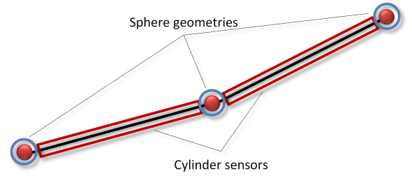
Fig. 15.2 Geometries associated to a Wire.
To make the wire interact with the rest of the simulation, it is also consisting of geometries. The geometries cause the wire to be able to collide with other geometries. A wire consists of two types of geometries:
Sphere geometries: Each lumped element (node with a rigid body) will be represented as a sphere (blue in above figure), with a radius derived from the radius of the wire/segment. This geometry collides with other geometry and creates contacts which the solver will see.
Cylinder geometries: Between each lumped element (node), a cylinder (red in the above figure) will be kinematically transformed between time steps. This cylinder is used for detecting contacts between the Wire and edges on other geometries. There are no contacts generated between this cylinder and other geometries that the solver will see.
Similar to an ordinary agxCollide::Geometry, the API for the wire has a number of methods to control which other geometries can collide with the geometries in the wire:
void setEnableCollisions(const agx::RigidBody* body, bool flag);
void setEnableCollisions(const agxCollide::Geometry* geometry, bool flag);
void addGroup(unsigned id);
void addGroup(const agx::Name& name);
15.6.4. Operations on a Wire
A wire is created in a routing process described below. When a wire is created it can be merged/cut/split/reversed for more information see Section 15.11.
15.6.5. Devices used with wires
A wire can be routed together with various devices, for example a Winch and WireSimpleDrumController. A winch is a device which resembles a real life winch. It is capable of pulling in and feeding out wire just as a winch would. The mass of the wire that is pulled into a winch will not be simulated.
15.7. agxWire::Node
A Node is used for routing a wire and to attach a wire to a certain RigidBody. A Node defines a point through which a wire is forced to pass. This means that a Node attached to a RigidBody will give a 1-1 interaction between the RigidBody and the wire.
The nodes are stored in an ordered list. If a wire hasn’t been cut or detached, the first and last nodes are the ones the user used when creating the wire.
BodyFixed nodes (or lumped element nodes) are nodes that will appear at a certain fix distance from each other or a multiple of that distance. Each body fixed node is placed in the center of mass of a rigid body, which carry some of the mass of the wire. The dynamic resolution makes body fixed nodes (and their bodies) disappear and appear as the tension increases and decreases to keep the simulation numerically stable. A distance constraint is only defined between two body fixed nodes.
Note
Body fixed nodes can also be used as fixed connection points on bodies. They can be located at arbitrary relative positions to that body.
Note
If collisions between the rigid body and the wire are enabled, it is important to place the BodyFixedNode so that the whole wire is initially non-overlapping. This includes especially one extra wire radius around the attachment point. So:
agx::RigidBodyRef body = new agx::RigidBody(new agxCollide::Geometry(new agxCollide::Box(agx::Vec3(1, 1, 1))));
// ...
agxWire::WireRef wire = new agxWire::Wire(0.1, 10);
wire->add(new agxWire::BodyFixedNode(body, agx::Vec3(1 + 0.1, 0, 0))); // Note the extra 0.1
Eye nodes are nodes that can never start or end a wire. They consist of two points that both are fixed relative a rigid body which is NOT part of the wire. Their purpose is then to make the rigid body slide along the wire.
ShapeContact nodes work as eye nodes except for two major differences: they come and go as the wire collides and slips off geometries and they slide (with friction) along edges (see Section 15.8.1) of shapes.
Free nodes (could also be called temporary lumped nodes) are used for routing. They are kept as long as the wire is numerically stable. If the actual position of a free node along the wire will give us stability problems but still is considered necessary to keep to retain the orientation and most of the energy, the node may travel along the wire to a position where the tension could be handled by the solver. If the free node isn’t necessary to keep it is removed forever. When a contact between the wire and geometry is supposed to be removed, the contact node is transformed into a FreeNode instead, to preserve the wire orientation.
15.7.1. agxWire::BodyFixedNode
BodyFixedNode is a node that attaches a wire to a point relative to a RigidBody.
// Arguments: the body and an attachment point relative the body
agx::BodyFixedNodeRef bf = new agxWire::BodyFixedNode( body, Vec3( 1,0,1 ));
15.7.2. agxWire::EyeNode
EyeNode is a node that can slide along a wire. It has two friction parameters, in two separate directions. Positive is specifying friction when a body is sliding along the wire towards the end of the wire, Negative, is when a body is sliding towards the beginning of a wire. The beginning of a wire is determined as the first point of routing.
An EyeNode can also specify a point and a normal, which makes it possible to attach a RigidBody and make it rotate as the wire moves and vice versa.
agxWire::EyeNodeRef eye = new agxWire::EyeNode( slidingObject.getRigidBody(),
                                                    Vec3( 1,0,1 ),    // First point relative to body.
                                                    Vec3( -2,0,0 ) ); // Vector pointing from first point
                                                                      // To the second point
The third argument is a vector pointing out the direction and distance to the second point of attachment between the wire and the rigid body.
An EyeNode can also have a radius which determines whether a Link with a specified radius can pass through or not.
To specify the friction of the wire sliding through the eye, use the wire material:
eyeNode->getMaterial()->setFrictionCoefficient( 0.5 );
It is also possible to specify different friction in different directions:
eyeNode->getMaterial()->setFrictionCoefficient( 0.5, agxWire::NodeMaterial::NEGATIVE );
eyeNode->getMaterial()->setFrictionCoefficient( 0.5, agxWire::NodeMaterial::POSITIVE );
To have the eye node constrained to an area instead of a point the node can be attached to an agxWire::EyeNodeArea. The eye node is in this case attached to a rigid body that is constrained to another rigid body.
// Rigid body that is associated with the area in which the eye node can move
agx::RigidBodyRef eyeNodeAreaBody = new agx::RigidBody( eyeNodeAreaGeometry );
simulation->add( eyeNodeAreaBody );

agx::RigidBodyRef eyeBody = new agx::RigidBody(); // Eye node body
eyeBody->setPosition( position ); // Initial position should be inside the constraining area.
simulation->add( eyeBody );

agxWire::WireRef wire = new agxWire::Wire( wireRadius, wireResolution );
wire->add( new agxWire::FreeNode( startPosition ) );
wire->add( new agxWire::EyeNode( eyeBody, agx::Vec3() ); // Body position should be the same as node position.
wire->add(  new agxWire::FreeNode( endPosition )  );
simulation->add( wire );

// An area definition that specifies the constraining area. It is specified in body coordinates.
agxWire::AreaDefinitionRef areaDefinition = new agxWire::CircularAreaDefinition( localPoint,
                                                                                 radius,
                                                                                 eyeNodeAreaBody,
                                                                                 localDir,
                                                                                 eyeNode );

agxWire::EyeNodeAreaRef eyeNodeArea = new agxWire::eyeNodeArea( areaDefinition );
simulation->add( eyeNodeArea );
The area definitions available are agxWire::CircularAreaDefinition and agxWire::ConvexAreaDefinition.
The circular area definition is defined by a local point on the constraining body that will be center of the circle, a local direction on the constraining body and a radius.
CircularAreaDefinition::CircularAreaDefinition( const agx::Vec3& localCenter,
                                                      agx::Real radius,
                                                      agx::RigidBody* constrainingBody,
                                                const agx::Vec3& localDir,
                                                      agxWire::EyeNode* eyeNode );
The convex area definition is defined by a local point on the constraining body, a local direction on the constraining body and a set of local points that is projected onto the plane specified by the point and direction.
ConvexAreaDefinition::ConvexAreaDefinition( const Vec3& localCenter,
                                                  Vector< Vec3 > localAreaCoordinates,
                                                  RigidBody* constrainingBody,
                                            const Vec3& localDir,
                                                  EyeNode* eyeNode )
It is also possible to create a custom area by creating a class that inherits from agxWire::AreaDefinition.
An example of how an eyeNodeArea is used is available in tutorial_wire1.cpp, Tutorial 8.
15.7.3. agxWire::FreeNode
FreeNode are nodes that can be used during the routing procedure of a wire. They are nodes that will disappear when the tension increases in the wire.
wire->add( new agx::FreeNode( Vec3( 52,2,10 ) ); // Position in world coordinates
15.8. Wire Material
The class agxWire::Wire stores an instance of an agx::Material. This material is used for two things:
Bulk attributes: Density is used to calculate the internal material properties for a wire. Whenever this material is updated with new properties, the physical properties are recalculated.
Surface attributes: The SurfaceMaterial part is used during contact processing to calculate restitution and friction like any other geometry collision. It is possible at any point in time to change the material of a segment:
const agx::Real resolution = 1.0;
const agx::Real radius = 0.01;
// Create a material
agx::MaterialRef wire_material = new agx::Material("wire_material");
simulation->add( wire_material );

agxWire::WireRef wire1 = new agxWire::Wire( radius, resolution )

// Associate the new material to this Segment
wire1->setMaterial( wire_material );

// Set properties
wire_material->getWireMaterial()->setYoungsModulusBend( 1E11 );
wire_material->getSurfaceMaterial()->setRoughness( 0.2 ); // Friction
It also possible to use the wire material when creating explicit ContactMaterials:
// Create an explicit contact material for this wire_material colliding
// with another material
agx::ContactMaterialRef wire_plastic_material = new agx::ContactMaterial( wire_material, plastic_material );

// Set the attributes of the explicit material
wire_plastic_material->setFrictionCoefficient( 0.5 );

simulation->add( wire_plastic_material );
The material used for a Wire is internally modified (for point friction) which makes it unsuitable for use with other geometries in a simulation.
Attention
Avoid using the same material for an agxWire::Wire as other agxCollide::Geometries.
15.8.1. Wire Friction
A wire can interact with other geometries in two ways:
A wire segment intersects a geometry and a ShapeContactNode is inserted, with an edge to move along. This when using the kinematic wire contact algorithm, which solve the dynamics, including friction, of shape contact nodes in a co-simulation.
A wire collides on the surface of another geometry. Either a rigid wire segment when using the dynamic wire contact algorithm, described in Section 15.17.2. or a BodyFixedNode.
Wire friction for BodyFixedNode’s and for the DynamicWireContact is defined as friction for any two geometries colliding, see Section 11.15 about materials.
Wire friction for a ShapeContactNode is defined both along the wire and along an edge defined orthogonal to the wire direction. See Fig. 15.3 for an illustration. When the wire (iii) is in contact (v) with a geometry (iv) and sliding along its edge (vii) we find a friction force (ii) along the edge. If the normal force (i) is small enough we see sliding friction, otherwise the contact will not move. The algorithm for defining edges for a ShapeContactNode make use of the wire direction and the local curvature of the shape the wire is in contact with.
To distinguish friction along the wire and along the edge for a ShapeContactNode primary (along the wire) and secondary (along the edge) friction direction is specified to set them differently. By default the wire friction coefficients are the same as defined for the contact material for a wire-geometry contact. Creating an explicit contact material the default wire friction coefficients can be overridden by setting the wire friction coefficient.
// Create an explicit contact material for this wire_material colliding
// with another material
agx::ContactMaterialRef wire_plastic_material = new agx::ContactMaterial( wire_material, plastic_material );

// Set the wire friction coefficient along the wire
wire_plastic_material->setWireFrictionCoefficient( 0.5, ContactMaterial.PRIMARY_DIRECTION );
// Set the wire friction coefficient along the shape contact edge
wire_plastic_material->setWireFrictionCoefficient( 0.1, ContactMaterial.SECONDARY_DIRECTION);

simulation->add( wire_plastic_material );
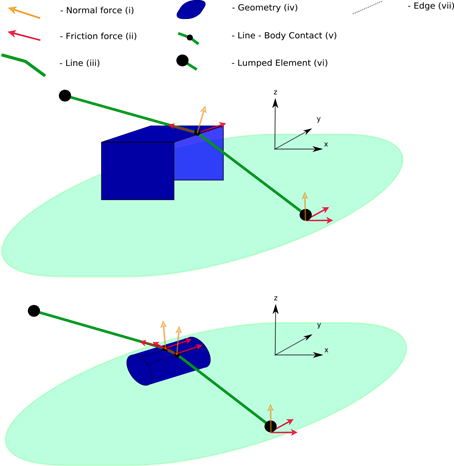
Fig. 15.3 Illustration of wire friction.
15.9. Creating a agxWire::Wire
Below is a description of the process of creating a wire.
15.9.1. Routing a wire
A wire is placed into the world by a routing process. During the routing, winch controllers and nodes of various types are created and positioned attached to rigid bodies. The nodes are then added to the wire.
During wire routing, the route nodes added are stored locally in the wire. I.e. no communication occurs with the constraints. The wire has not been added to a simulation at this point. The routing ends when the wire is added to the simulation.
Attention
This means that adding a wire to the simulation should be done after all the routing is done.
When the first node is added, a check for a possible winch controller at the beginning of the wire is done. If one is present, and it for example does not have auto-feed enabled, we have to take care of the rolled in length and count that to the total routed length.
For all nodes added after the first one, we calculate the current route length. If the route length does not exceed the total length of the wire, we add the node to the local list of routed nodes.
15.9.1.1. Process for routing a wire
Initialization
Create all bodies (involved in routing)
Create WinchControllers at relative position to bodies (or in the world)
Create eyes, at positions relative to bodies
Position bodies at their correct positions.
Routing:
Route beginning of wire either through a winch, a BodyFixedNode, a ConnectingNode or a FreeNode.
Route through WinchController (wire->add())
Route through eyes (wire->add())
Route through final WinchController (wire->add()) or
You always have to end the route with a WinchController, BodyFixedNode, ConnectingNode or a FreeNode.
Add wire to simulation
Simulate.
It is always important to remember to always position the rigid bodies/Nodes before the routing process starts. This is the same requirement as when configuring other constraints in AGX.
15.9.2. Add to simulation
When a wire is added to the simulation it will be assumed that the routing is finalized.
Starting at the end we check for winch controllers, if present, one of the following scenarios may occur:
Winch at both ends, both with auto-feed enabled.
Pulled in length for the end winch is set to zero and all superfluous wire is moved to the first winch.
Winch at both ends, first with auto-feed enabled and second with auto-feed disabled.
If this is the case, errors (warning messages, return false and ignoring the last winch during routing) occurs if the wire outside the winch is not long enough. Other than that this is a well-defined case.
Winches at both ends, first with auto-feed disabled and second with auto-feed enabled.
This means that auto-feed flag is used wrong. The purpose of the flag is to pull in all wire inside the first winch and then route while the length inside the first winch is changed during routing. If this case appears, all superfluous wire is put in the first winch, the one that does not have auto-feed enabled.
15.10. Rendering a agxWire::Wire
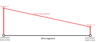
Rendering a wire is done using RenderIterators. Basically, a RenderIterator contains enough information to get a world position and tension of a control point in the wire. The code for agxOSG::WireRenderer can be found in <agx-dir>/agxOSG/src/WireRenderer.cpp,.h
agxWire::WireRef wire = createAWire();
simulation->add(wire);
simulation->stepForward();       // Take a time step
agx::Real refMaxTension = 1E4; // Just to get some reference for setting color/weight of a
                               // controlpoint in the spline

// Create a graphical representation of a spline in your rendering engine
Rendering::Spline *spline = new Rendering::Spline();

agxWire::RenderIterator it        = wire->getRenderBeginIterator();
const agxWire::RenderIterator end = wire->getRenderEndIterator();

// Loop through all the nodes in the wire
while ( it != end ) {
  const agxWire::Node* node = *it;

  // We can also read tension at the node to scale, control the rendering
  spline->add( node->getWorldPosition(), Real( 0.9 ) );
  ++it;
}
15.11. Wire operations
15.11.1. Cut a wire
To cut a wire there are two methods available:
// Cut a wire at the specified wire length
agxWire::Wire* agxWire::Wire::cut( const agx::Real& length , size_t minimumResolution, bool includeWinchPulledInLength = true );

// Cut the wire at the closest point one the wire
// from the specified position
agxWire::Wire* Wire::cut( const agx::Vec3& position, size_t minimumResolution );
Both methods return a pointer to the second part of the cut wire. The wire returned is already inserted into the simulation and is ready to use. The two wires does not share any information, so they can be removed independently from the simulation.
15.11.2. Merge two wires
Two wires can be merged into one using the merge method:
bool agxWire::Wire::merge( agxWire::Wire* wireToMergeWith );
An example:
agxWire::WireRef a = createAWire();
agxWire::WireRef b = createAWire();

a->merge( b );
In the above example b will be added to the end of a. This method will only work if the last node in a and the first node in b are FreeNodes.
Attention
To be able to merge two wires wire A and wire B, the last node of wire A and the first node of wire B have to be FreeNodes.
If the two end points to be merged are not at the same position, additional wire will be added to the last wire segment as a straight wire between the end of the first and beginning of the first. This means that the resulting wire length after a merge is always >= length1+length2
The wire given as an argument to merge() will be deleted from the simulation. If no references are holding it, it will be deallocated.
15.12. Controlling wire resolution
The wire has an overall resolution controlled at construction or by using the method Wire::setResolutionPerUnitLength( agx::Real resolutionPerUnitLength );
However, in some cases you might want to have different resolution along the wire.
One typical scenario is where you have wire on a ship deck, and the wire goes into water for several kilometers and then up to another ship deck.
It would be a waste of resources to have the same resolution along the whole wire. On deck, you might want to have higher resolution and in the water, it can be enough with a lot less nodes during simulation.
This can be controlled using the HighResolutionRange class that is available for nodes.
First you need to identify a node on the wire which acts as the reference. Usually the begin or the end of a wire but intermediate nodes, such as eye nodes, may also be reference nodes for higher resolution. The high resolution range may be at any distance before or after the reference node along the wire (not necessarily overlapping the reference node).
agx::Real default_resolution = 0.1; // One node every 10 meters
agxWire::WireRef wire = new agxWire::Wire(0.01, default_resolution);
agxWire::WireWinchControllerref winch = new agxWire::WireWinchController(winch_body, agx::Vec3(0,0,0), agx::Vec3(1,0,0));
wire->add(winch);

double start_distance = 2; // Start of the range with higher resolution
double end_distance = 10;  // End of the range with higher resolution
agx::Real new_resolution = 2; // Two nodes every meter

  // Set the high resolution range. In this range the wire will get higher resolution.
winch->getStopNode()->getHighResolutionRange()->set( start_distance, end_distance, new_resolution );
You can also have several high resolution ranges along a wire. Also, you cannot reduce the resolution, only increase.
15.13. agxWire::WireWinchController
The class agxWire::WireWinchController is an implementation of a winch that can pull in and winch out wire.
It is based on a constraint (Prismatic) which means that it applies forces on a wire just as any other constraint or RigidBody in the system.
It has functionality to haul in Links (which it then automatically disables when it is winched in the winch). A Winch can only be routed to the beginning or the end of a wire.
A winch has a motor and a brake that can be controlled independently from each other.
Remember that a motor cannot hold a load a specific position by setting the speed to zero. This is related to the problem of non-holonomic constraints that occurs with all velocity constraints.
To hold a load a certain position, a holonomic (position) constraint should be used, in this case the winch brake.
For composite wires (wires with links in between) there is also the agxWire::Winch class. (see Section 15.21.3)
A winch is always attached to a RigidBody:
agxWire::WireWinchControllerRef winch = new agxWire::WireWinchController(
                              rigidBody,                              // RigidBody onto which sd is attached
                        agx::Vec3( 0, 0, -1 ),  // Position relative to rigidBody
                        agx::Vec3( 0, 0.0, -1); // Normal direction
A winch can be told to pull in any “loose” wire so that the wire is stretched after the routing:
winch->setAutoFeed( true );
Routing a wire to the winch is done by adding the winch to the wire:
// Add the winch to the wire, the second argument is the amount of wire pulled
// in to the winch at start.
wire->add( winch, wireLength );
The above call will result in that the winch will pull in all the resulting wire after it is routed.
A winch can be detached from a wire with a call to:
wire->detach(bool front);
where front has to be set to true if the winch is in the front end of the wire, false for the back.
The winching mechanism of a winch can be activated and controlled through the following API:
Set the maximum force for holding the wire (keeping velocity at 0):
void Winch::setBrakeForceRange( agx::Real brakeForce );
Set the desired winch in/out speed:
void Winch::setSpeed( agx::Real speed );
Set the maximum force by which the desired speed will be obtained:
void Winch::setForceRange( agx::Real winchForce );
The force applied by the winch motor and the winch brake can be accessed via:
auto winchForce = winch->getCurrentForce();

auto winchBrakeForce = winch->getCurrentBrakeForce();
Note
If all wire has been spooled out (agxWire::WireWinchController::getPulledInWireLength() reports zero), the forces reported will not be consistent.
We recommend that you avoid spooling out all wire. Instead stop the winch before all wire is spooled out, or detach the wire from the winch.
15.14. Wire-wire interaction
Wires can also collide with other wires. This functionality has to be explicitly enabled between pairs of wires that are supposed to be able to interact. The class agxWire::WireController controls this behavior.
To enable wire-wire interaction between two instances of agxWire::Wire:
agxWire::WireRef wire1 = createWire(); // Create a wire
agxWire::WireRef wire2 = createWire(); // Create a wire

// Enable wire-wire collisions between the two wires
agxWire::WireController::instance()->setEnableCollisions(wire1, wire2, true);
For stability of wire-wire interaction, the coefficient of restitution for the contact material between the two wires should be set to 0.
auto* cm = simulation->getMaterialManager()->getOrCreateContactMaterial(wire1->getMaterial(),
                                                                        wire2->getMaterial()); // Obtain the contact material
cm->setRestitution(0);
Also, the value of YoungsModulusBend for material of the respective wires should be set to realistic values.
wire->getMaterial()->getWireMaterial()->setYoungsModulusBend(1E9);
If a chain should be simulated instead of a relatively stiff wire, this can be achieved by turning off the bend resistance altogether, instead of setting it to zero:
wire->getMaterialController()->setIsBendResistant(false);
15.15. Reading tension/forces
After a time step (a call to simulation->stepForward()), the tension involving the wire is updated and available.
The tension at each node along the wire can be read through the specified node in the wire or through a point in space or a length along the wire.
15.15.1. Get tension given distance along wire or point in the world
The tension can be queried given a point in space, or a length from start along the wire. These two methods will do a linear search to find the correct point along the wire. The data will be returned into a struct: agxWire::WireSegmentTensionData containing various data. The data will be linearly interpolated between the nodes in the wire:
// Closest point to the wire will be used
double tension = wire->getTension( agx::Vec3(1,1,1) ).getAverageRaw();

// Get the tension in the wire a certain length along the wire
double tension = wire->getTension( 123 ).getAverageSmoothed(); // 123 m from start
15.15.1.1. Get tension given node
The node tension data, agxWire::WireNodeTensionData, contains data for two segments - the segment before and the segment after the node. I.e., the tension exactly before and exactly after the node.

for ( agxWire::RenderIterator i = wire->getRenderBeginIterator(); i != wire->getRenderEndIterator(); ++i )
{
  double tension = 0;
  agxWire::WireNodeTensionData data = wire->getTension( *i ); // Get tension at the node
  tension = data.getAverageSmoothed();
}
In comparison to “get tension given distance along wire”, fetching data given node is computationally much cheaper.
15.15.1.2. Tension at nodes
The tension along a wire isn’t continuous - so beware of, and think of, what it means to read tension given nodes. Consider a closed Shark Jaw, as the two pictures below, modeled with an eye node (green sphere) that has infinite friction.
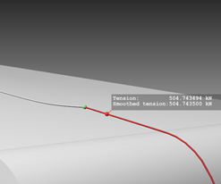
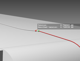
In this example, tension drops instantaneously from 504 kN to 7 kN over the eye node making it hard to interpret the exact tension value at the node. By definition (internally) the node at the end of a segment is carrying the tension data, i.e., if one ask the node what tension it feels it can either be 504 kN or 7 kN depending on in which way the wire is routed (or after reverse). It’s important to be consistent and think twice which value one expects in this special case.
Of course it becomes more convenient with our data holder, agxWire::WireNodeTensionData, which contains data for the segment before and after the node. But following the above definition, agxWire::WireNodeTensionData::getRaw(), returns the raw tension value from the segment before the node.
15.15.2. Normal force between a geometry and the wire
To get the normal force between a specified geometry and a wire you first have to locate a shape contact node in the wire which is interacting with the specific geometry, then you can query the node’s contact material for the normal force magnitude.
for ( agxWire::RenderIterator i = wire->getRenderBeginIterator(); i != wire->getRenderEndIterator(); ++i )
{
  double magnitude = 0;
  // Tension is only available at body fixed nodes
  agxWire::ShapeContactNode *cn = i.get()->getAsShapeContactContact();
  if (cn)
    magnitude = cn->getMaterial()->getNormalForceMagnitude();
}
15.16. Applying forces to a wire
If you want to simulate for example drag in water, wind, buoyancy or other external forces on a wire, you can do this with a ForceField. A ForceField will be updated inside the solve stage. This means that the callback in a user ForceField must never make any structural changes to the system. The only allowed operations is applying torque/forces onto rigid bodies, all other operations (except reading data) should be strictly avoided.
Below is a code snipped that creates a custom ForceField which applies forces to each rigid body of a wire.
// Derive from baseclass agx::ForceField
class MyForceField : public agx::ForceField
{
  public:
    MyForceField( agxWire::WireRef wire )
      : m_wire( wire ) {}

    // Virtual method called from within the solver
    virtual void updateForce( agx::DynamicsSystem* ) AGX_OVERRIDE
    {
      if ( m_wire == 0L )
        return;

      // Iterate over all nodes in the wire
      agxWire::RenderIterator it = m_wire->getRenderBeginIterator();
      while ( it != m_wire->getRenderEndIterator() ) {
        agxWire::Node* node = *it;
        // Check for internal, dynamic, mass nodes.
        if ( node->getType() == agxWire::Node::BODY_FIXED )
          node->getRigidBody()->addForce( calculateForce( node ) ); // Apply the force

        ++it;
      }
    }

  protected:

    // Some method for calculating a force
    // Could be calculating gravity, windforce, buoyancy or something else
    agx::Vec3 calculateForce( const agxWire::Node* node ) const
    {
      return agx::Vec3( agx::PI );
    }

  protected:
    agx::observer_ptr< agxWire::Wire > m_wire;
};

...
// Add the custom force field to a simulation
simulation->add( new MyForceField( wire ) );
15.17. Wire collisions and contacts
Up until this point the described agxWire::Wire contact behavior assumes that the default wire contact model is used. This model is called “default kinematic contact model”. There are two other models to consider, resulting in improved interaction fidelity.
Default kinematic contact model – Default model with unconditionally stable behavior
Dynamics wire contact model – Most dynamic/realistic behavior
15.17.1. Default kinematic contact model
One of the features of a kinematic model is that it is unconditionally stable. Wire collisions result in kinematic nodes (agxWire::ShapeContactNode) on the collided geometry.
To achieve highest performance combined with stability under high tension the default kinematic contact model is recommended.
When modeling of complex scenes with complex geometry wire collision can be computationally expensive. Collision between wires and complex geometry is not recommended when high performance is prioritized. Instead specific wire collision geometries are recommended to be used. I.e. position geometries containing one box or one cylinder to represent the complex geometry for the wire collisions (low interaction fidelity).
15.17.1.1. Wire kinematic model for AGX versions previous 2.19
For AGX versions previous 2.19 the kinematic contact model generated agxWire::ContactNodes at collision. The ContactNode is now deprecated and replaced with the ShapeContactNode which handle all shapes and has no restrictions on the number of shapes per geometry. New from 2.19 is that the wire has a class called WireShapeContactController replacing a previous class called WireContactController.
Restoring a wire stored from a version of AGX lower than 2.19 could include ContactNodes. The restored wire by default use the old wire contact controller. All contact nodes can be converted to shape contact nodes for a specific wire. For the wire to generate shape contact nodes from future interactions, the contact controller type must be changed from OLD_CONTACT_CONTROLLER to SHAPE_CONTACT_CONTROLLER.
// Saves simulation including a wire
agxStream::InputArchive& storedScene;
// Wire object to restore
agxWire::Wire* wire;

// Choose to use the shape wire contact controller,
// for shape contact node generation at collision
wire->setActiveContactControllerType(agxWire::SHAPE_CONTACT_CONTROLLER);

//convert all contact nodes to shape contact nodes
wire-replaceContactNodesWithShapeContacts();
15.17.2. Dynamic wire contact model
For a more realistic/fully dynamic behavior of wire/geometry interaction is required the Dynamic wire contact model is recommended. This model introduces new bodies, as part of the wire, wherever the wire has collided. It is therefore not expected to demonstrate the same stability under high tension as the kinematic model.
The dynamic wire contact model is enabled per geometry:
agxCollide::GeometryRef geometry = new agxCollide::Geometry();
agxWire::WireController::instance()->setEnableDynamicWireContacts(geometry, true);
This means that all wires will generate dynamic contacts when colliding with a geometry where the dynamic wire contacts are enabled. A limitation of the current implementation is that if different behavior is wanted from two different wires two different geometries must be used.
15.18. Automatic wire split for performance enhancement
agxWire::Wire support a notion of kinematic splitting during simulation. AGX Dynamics has an automatic partitioner which can analyze a system and split a simulation into subsystems (Section 36.5.2.3). This allows for the task/threading system to solve different parts in different threads. Thus improving performance in the overall system.
// Enable kinematic splitting for a wire
wire->setEnableSplitting( true );
By enabling the kinematic splitting for a wire, we allow for the system to introduce kinematic bodies along the wire, but only intermittent during one time step. Which of the bodies in the wire that are made kinematic will be determined by the splitting algorithm. To avoid artifacts, the place for splitting will be moved between time steps.
For wires under high tension it might not be possible for the splitting algorithm to introduce a kinematic body. This would potentially create unstable/unrealistic simulations.
15.19. Simulating a Pulley/Sheave/Gypsy Wheel
A sheave is a pulley with a grooved wheel for holding a belt, wire rope, or rope. The grooved wheel spins on an axle or bearing inside the frame of the block. This allows the wire or rope to move freely minimizing friction and wear on the cable. Sheaves can be used to redirect a cable or rope, lift loads, and transmit power. ( from Wikipedia)
A Gypsy wheel is usually a motorized Sheave, meaning it is used for pulling in/out chain. The chain will have infinite friction due to mechanical jamming.
Commonly a cylinder Shape is used for modeling a Sheave. However a problem is that the wire can easily slip of the cylinder, especially if the cylinder is narrow in comparison to the wire radius. To assign a sheave geometry the “Pulley” property:
// Assign the "Pulley" property to a Geometry (which contains a Cylinder shape)
sheaveGeometry->getPropertyContainer()->addPropertyBool("Pulley", true);
This will tell the Wire contact algorithms to only create contact nodes at the center-line of a cylinder.
A Gypsy wheel, which is a motorized pulley can be defined in a similar manner:
// Assign the "Gypsy" property to a Geometry (which contains a Cylinder shape)
gypsyGeometry->getPropertyContainer()->addPropertyBool("Gypsy", true);
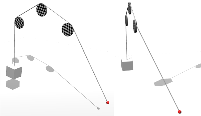
Fig. 15.6 Screenshot from the script wire_pulley.agxPy illustrating the use of the “Pulley” property. Here we can see that the wire is not slipping of the pulleys, even if the winch is pulling the wire sideways.
15.20. Hydro- and aerodynamics
A wire is affected by the fluid that surrounds it. A WindAndWaterController can be used to simulate the affects in water, air and other fluids, see Section 21.
15.21. Connecting wires, agxWire::Link
In general, an agxWire::Wire has no knowledge of neighboring connected wires. So, for example if one would like to connect a wire to a chain using a swivel, or wires of different radii using a shackle, or three wires connected through a tow plate – certain functionalities of the wire would not work as expected since all features are handled locally in the agxWire::Wire object.
agxWire::Link enables such functionality to work over connected wire segments. A link contains a user defined rigid body (with arbitrary geometry), a number of connecting wires and algorithms to transfer functionality between the wires.
15.21.1. Features
An agxWire::Link can have an arbitrarily number of connections. Typically, one or two connections is recommended for all functionality to be enabled.
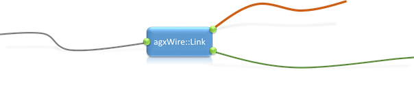
Fig. 15.7 A link with a number of different wire segments connected to it.
The mass of a link is normally relatively small in relation to the tension the connected wires could have, so an agxWire::Link includes additional stabilization constraints when the link is exposed to large forces.
15.21.2. Configuration
For simplicity, assume this configuration:
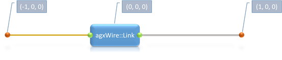
Fig. 15.8 The most common configuration where two wire segments are connected with a link in between.
Two wires connected to a link. Wire 1 has a free begin at (-1, 0, 0), the link positioned in the origin and Wire 2 ends in a free end at (1, 0, 0). Create the wires and the link:
agxWire::WireRef wire1 = new agxWire::Wire( wire1Radius, wire1Resolution );
agxWire::WireRef wire2 = new agxWire::Wire( wire2Radius, wire2Resolution );

// Link rigid body with box geometry.
agx::RigidBodyRef linkRb = new agx::RigidBody( new agxCollide::Geometry( new agxCollide::Box( linkHalfExtent ) ) );
linkRb->setPosition( 0, 0, 0 );
agxWire::LinkRef link = new agxWire::Link( linkRb );
The link must be positioned any time before the wires are initialized. When the wires are initialized the current position of the link defines the lengths of wires.
The link has to know where it’s connected to the wires. A link is either connected to a wire’s begin or end position of a wire and there are several ways of defining this.
Connection type from a links point of view:
/**
Connection type of the wires connected to this link, i.e., if this
link should be attached to begin or end of the wire.
*/
enum ConnectionType
{
  WIRE_BEGIN         = 0,    /**< Link attached at begin of wire. */
  WIRE_END           = 1,    /**< Link attached at end of wire. */
  INVALID_CONNECTION = 0xFF  /**< Invalid connection, e.g., if this link isn't connected to a give wire. */
};
Defining the connections to a link is only a mapping of how the wire composition relates. No nodes are added to the wires!
15.21.2.1. Routing with explicit connection type
Explicitly assigning the connection type:
// on the link is given in the link's coordinate system, and
// could in this case be: (-linkHalfExtent.x(), 0, 0)
link->connect( wire1, wire1ConnectionPosition, agxWire::Link::WIRE_END );

// The link is connected to Wire 2 begin. The connection position
// on the link is given in the link's coordinate system, and
// could in this case be: (linkHalfExtent.x(), 0, 0)
link->connect( wire2, wire2ConnectionPosition, agxWire::Link::WIRE_BEGIN );
The link now has two connections and now we can route the above system:
// Wire 1 first free node.
wire1->add( new agxWire::FreeNode( -1, 0, 0 ) );
// Add the link. The wire will find out how it relates to the
// link and add a node to the wire route. 'false' means that
// the wire shouldn't update the connection type and instead
// fail (return false) if the connection type is a mismatch.
wire1->add( link, false );

// Wire 2 starts at the link...
wire2->add( link, false );
// ...and ends at the free end (1, 0, 0).
wire2->add( new agxWire::FreeNode( 1, 0, 0 ) );
The above route is a valid route and the second argument to the add method also assures the connections are valid given the wanted route. If the connection type isn’t that important, pass true as second argument (default is true) and the wire will match and update the connection type to the link. Example:
link->connect( wire1, wire1ConnectionPosition, agxWire::Link::WIRE_END );
print( link->getConnectionType( link->getConnectingNode( wire1 ) ) ); // "WIRE_END"
// Routing the other way around. Link is attached at wire begin.
wire1->add( link );
wire1->add( new agxWire::FreeNode( -1, 0, 0 ) );
print( link->getConnectionType( link->getConnectingNode( wire1 ) ) ); // "WIRE_BEGIN"
15.21.2.2. Routing with implicit connection pair
agxWire::Link has a static utility method to configure the most common configuration (Fig. 15.8), so configuring such setup can be done with one call:
// Wire 1 will get WIRE_END connection type and Wire 2 WIRE_BEGIN.
agxWire::Link::connect( wire1, wire1ConnectionPosition, link, wire2, wire2ConnectionPosition );
And the actual routing:
wire1->add( new agxWire::FreeNode( -1, 0, 0 ) );
wire1->add( link );

wire2->add( link );
wire2->add( new agxWire::FreeNode( 1, 0, 0 ) );
15.21.2.3. Routing and connecting – all in one call
When routing, a wire has the possibility to know, given nodes already added or not, which connection type a wire should have relative the link. Routing and connecting the system in (Fig. 15.8):
wire1->add( new agxWire::FreeNode( -1, 0, 0 ) );
// Will connect to the link and give Wire 1 connection type WIRE_END.
wire1->add( link, wire1ConnectionPosition );

// Will connect to the link and give Wire 2 connection type WIRE_BEGIN.
wire2->add( link, wire2ConnectionPosition );
wire2->add( new agxWire::FreeNode( 1, 0, 0 ) );
15.21.3. agxWire::Winch
The agxWire::Winch class is derived from the class agxWire::WireWinchController. It adds a few additional features:
Can pull in links.
Can pull out links.
Can store completely inactive wires and their rest lengths.
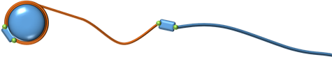
Fig. 15.9 Schematic figure of a wire composition with two wire segments. One completely pulled in segment (orange) connected to an (also inactive) pulled in link. The active wire (blue) is connected to the inactive wire through another active link.
An agxWire::Winch simulates a linear winch all units of forces are in Newton (N).
15.21.3.1. Length of a wire that hasn’t been routed?
The agxWire::Wire object doesn’t have a pre-defined length. The length of a wire is only defined by the pulled in length in a winches plus the active distance outside. So for a wire to have a length it must have at least two nodes.
A completely pulled in wire doesn’t have active nodes. It only has a connection to a link – which also is inactive (i.e., no position). So for a winch to be able to properly configure a wire that never has been active, one has to ‘report’ the length of completely pulled in wire segments to the winch.
How to create an **agxWire::Winch*, please have a look at the agxWire::WinchController section, the constructor and API are identical.*
// The completely pulled in wire segment.
agxWire::WireRef inactiveWire = new agxWire::Wire( inactiveWireRadius, inactiveWireResolution );
// The active wire segment that's connected to the winch.
agxWire::WireRef activeWire = new agxWire::Wire( activeWireRadius, activeWireResolution );

// Create the winch (API identical to agxWire::WireWinchController).
agxWire::WinchRef winch = new agxWire::Winch( winchRb, winchConnectionPoint, winchDirection );

// Report the inactive wire segment to the winch.
winch->add( inactiveWire, inactiveWireLength );
15.21.3.2. Routing with completely pulled in wire segments
The most important thing to remember when routing with inactive segments is not to forget to define the link connections. The following code snippet routes a system similar to Fig. 15.9 but with two inactive, completely pulled in, segments:
// The completely pulled in wire segments.
agxWire::WireRef inactiveWire1 = new agxWire::Wire( inactiveWireRadius, inactiveWireResolution );
agxWire::WireRef inactiveWire2 = new agxWire::Wire( inactiveWireRadius, inactiveWireResolution );
// The active wire segment that's connected to the winch.
agxWire::WireRef activeWire1 = new agxWire::Wire( activeWireRadius, activeWireResolution );
// The other active wire segment.
agxWire::WireRef activeWire2 = new agxWire::Wire( activeWireRadius, activeWireResolution );

// DEFINE THE CONNECTIONS:
// Inactive wire 1 is connected to inactive wire 2.
agxWire::Link::connect( inactiveWire1, wire1ConnectionPosition, link1, inactiveWire2, wire2ConnectionPosition );
// Inactive wire 2 is connected to active wire 1.
agxWire::Link::connect( inactiveWire2, wire1ConnectionPosition, link2, activeWire1, wire2ConnectionPosition );
// Active wire 1 is connected to active wire 2.
agxWire::Link::connect( activeWire1, wire1ConnectionPosition, link3, activeWire2, wire2ConnectionPosition );

// Create the winch (API identical to agxWire::WireWinchController).
agxWire::WinchRef winch = new agxWire::Winch( winchRb, winchConnectionPoint, winchDirection );

// Report the inactive wire segments to the winch.
winch->add( inactiveWire1, inactiveWire1Length );
winch->add( inactiveWire2, inactiveWire2Length );

// Begin route from winch to link2. Note that the initial pulled in
// length is how much of activeWire1 that's pulled in.
activeWire1->add( winch, initialPulledInLength );
activeWire1->add( link3 );

activeWire2->add( link3 );
activeWire2->add( new agxWire::FreeNode( wire2EndPosition ) );

// Only the active wires have to be added to the simulation.
simulation->add( activeWire1 );
simulation->add( activeWire2 );
Only active wires have to be added to the simulation!
15.21.3.3. Pulled in length
The agxWire::Winch and agxWire::WireWinchController return the same value for pulled in length – i.e., the amount pulled in of the current segment.
An agxWire::Winch has a few additional methods that support the inactive, totally pulled in, wire segments. Example:
agx::Real inactiveWireLength = 10.0;
agx::Real activeWirePulledInLength = 5.0;

// Add inactive wire, 10 m long.
winch->add( inactiveWire, inactiveWireLength );
// Add the winch to the active wire with 5 m pulled in length initially.
activeWire->add( winch, activeWirePulledInLength );

print( winch->getPulledInLength() );      // "5.0"
print( winch->getTotalPulledInLength() ); // "15.0"
print( winch->getNumPulledInWires() );    // "1"

// Remove the inactive wire.
winch->remove( inactiveWire );

print( winch->getPulledInLength() );      // "5.0"
print( winch->getTotalPulledInLength() ); // "5.0"
print( winch->getNumPulledInWires() );    // "0"
15.21.4. agxWire::Link:Algorithm
The link functionality is coupled to separate implementations of agxWire::Link::Algorithm’s. A link algorithm receives callbacks with the link at different stages of a time step and when the link changes state from enabled to disabled, and vice versa.
The (current) default algorithms:
Detect approaching (sliding) nodes and spawn new algorithms given node type. E.g., from the link’s point of view, when a winch is approaching.
Not fully pulled in or out link algorithm. The state before a segment is completely pulled in, the link is on a cylindrical joint, and this algorithm handles when the state changes to fully pulled in or out wire segments.
The first inactive link in a winch receives callbacks to detect when it’s time to go active.
Enables high resolution ranges to spread over wire segments.
It’s possible to implement your own or add extra (i.e., not default) link algorithms. If you are implementing your own link algorithm it’s important to not store/keep a configuration dependent state. Configuration dependent states could be a wire, a start and an end node (which gives a direction). The reason for this constraint is because the link will never know if a wire has been reversed or cut in two, when a node has been removed, been merged with another wire, removed from the simulation etc..
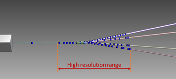
Fig. 15.10 High resolution range over link with five connections.
15.21.4.1. Optional link algorithms
For usability or performance reasons, some link algorithms are optional.
15.21.4.2. Contact stabilizing algorithm
In some cases, where the tension is high in two or more connections, the link could become unstable when in contact with other objects. This optional link algorithm monitors the tension in the connections and creates additional, stabilizing constraints when the link is in contact with another object.
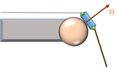
Fig. 15.11 Case where it could be suitable with a contact stabilizing algorithm.
The contact stabilizing algorithm uses its own version of a contact execute filter. It’s easy to implement a filter, e.g., this filter that matches a rigid body with name ‘sternRoller’:
#include <agxWire/LinkAlgorithms.h>

class SternRollerMatcher : public agxWire::LinkObjectStabilizingAlgorithm::LinkExecuteFilter
{
  public:
    SternRollerMatcher( const agxWire::Link* link )
      : agxWire::LinkObjectStabilizingAlgorithm::LinkExecuteFilter( link ) {}

    // otherGeometry is overlapping the link - check if match.
    virtual bool matchOther( const agxCollide::Geometry* otherGeometry ) const
    {
      return otherGeometry->getRigidBody() != 0L && otherGeometry->getRigidBody()->getName() == "sternRoller";
    }
};
So when matchOther returns true AND the tension is high enough, extra constraints will be added to stabilize the link.
There are some already implemented filters. For example filters that match a property (in agx::PropertyContainer) in either a geometry or a rigid body. Example with geometry:
// Filter that checks a geometry's property container.
agxWire::LinkObjectStabilizingAlgorithm::GeometryPropertyBoolFilterRef geometryPropertyFilter =
  new agxWire::LinkObjectStabilizingAlgorithm::GeometryPropertyBoolFilter( "stabilize", link );

link->add( new agxWire::LinkObjectStabilizingAlgorithm( geometryPropertyFilter ) );

// Enables algorithm when the link is in contact with this geometry.
someGeometry->getPropertyContainer()->addPropertyBool( "stabilize", true );
Example with rigid body:
// Filter that checks a rigid body's property container.
agxWire::LinkObjectStabilizingAlgorithm::GeometryPropertyBoolFilterRef rbPropertyFilter =
  new agxWire::LinkObjectStabilizingAlgorithm::GeometryPropertyBoolFilter( "stabilize", link );

link->add( new agxWire::LinkObjectStabilizingAlgorithm( geometryPropertyFilter ) );

// Enables algorithm when the link is in contact with this rigid body.
someRigidBody->getPropertyContainer()->addPropertyBool( "stabilize", true );
15.21.5. Known limitations
15.21.5.1. Links and EyeNodes
A Link can not slide through an EyeNode. This is a feature that might be added in a future release of AGX Dynamics.
15.21.5.2. Loops in the configuration
A valid link-wire composition cannot have loops. There are recursive sections in the code, assuming a tree structure of the connection assembly. A link can only detect a loop if the user tries to connect the same wire twice to a link, and other than that, no runtime checks nor parsing of the current configuration to detect loops are made.
Fig. 15.12 Loops in the link connections is undefined.
This loop limitation prevents the user from creating a lasso using links and the connect-interface. But the reason for links is functionality such as pulling them into/out from winches, and pulling a lasso into a winch doesn’t often make that much sense.
The more reasonable scenario when pulling a lasso into a winch is that the winch stops, due to jamming (or something similar). To achieve such behavior:
Connect the main wire to the link (i.e., not the lasso wire). The link should only have one mapped connection, making the link a so called ‘end link’. I.e., the link defines the end of a link-wire composition.
Create and route the lasso wire only using explicit connections. Explicit connections could be separate bodies locked to the link body or body fixed/connecting nodes with the link body as the rigid body.
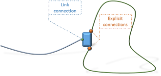
Fig. 15.13 Lasso configuration so that a winch will automatically stop when the lasso is about to be pulled in.
15.21.5.3. Length of connections and winches
The maximum distance from a connection point, on the link surface, to the link center of mass, must be less than one meter for the winches to work with the link. In principle, this means that a somewhat symmetric link can’t be longer than two meters AND be pulled into or out from a winch. If winches aren’t involved, there’s no limitation in the connection lengths.
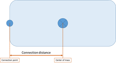
Fig. 15.14 Definition of the connection distance going from the connection point to the center of mass.
15.21.6. Controlling Link behaviour
15.21.6.1. Link and bend
Connecting wires to small link objects are often problematic when simulating offshore operations due to the wire tension to link mass ratio difference. Early, AGX have had support for such connections, supporting stable simulation with wires and links, even when the system involves extreme potential energies. The solution to the initial problem has been to have a variable stiffness of the bend constraint over the link, i.e., controlling more degrees of freedoms to filter out high frequencies.
This control of the bend stiffness has been, and will always be, handled internally. When the tension is low the bend was completely ignored making the connection look like a ball joint type of connection. I.e., the link could rotate freely about the connecting point. This type of connection behavior isn’t always desirable and the user should be able to control the bend stiffness when the link isn’t under extreme stress.
15.21.6.2. Link and twist
If the wire going out from a link connection defines an axis, the twist is defined to be the rotation about that axis.
Until now, this degree of freedom has been completely ignored by the wire. Mainly because there’re absolutely no information about it because the wire uses 3 DOF (particle) bodies internally. Bending is still defined when the geometry of this exist given three control points along a wire.
Since twist is a completely new concept for the links, consider it experimental, and more work has to be done to figure out the API to control all desirable “effects” of twisting a link about a wire.
15.21.7. Introducing interface to a Link Node and Connection Properties
15.21.7.1. agxWire::ILinkNode
This new node is only an interface to the implementation of the special node used when connecting an agxWire::Wire to an agxWire::Link. At this moment, the interface is minimalistic but can be extended easily for future features.
/**
Interface class for nodes connected to links.
*/
class AGXPHYSICS_EXPORT ILinkNode : public agxWire::ConnectingNode
{
  public:
    /**
    \return the connection properties for the connection between the wire and the link
    */
    virtual agxWire::ILinkNode::ConnectionProperties* getConnectionProperties() const = 0;
};
15.21.7.2. agxWire::ILinkNode::ConnectionProperties
New object holding parameters and properties of a connection between a wire and a link. Currently it’s small and it’ll be extended/changed when we fully understand these connections.
/**
Object holding parameters, such as bend and twist stiffness,
related to wire to link connections.
*/
class AGXPHYSICS_EXPORT ConnectionProperties
{
  public:
    /**
    Default constructor, with default bend and twist stiffness disabled.
    */
    ConnectionProperties();

    /**
    Construct given bend- and twist stiffness.
    */
    ConnectionProperties( agx::Real bendStiffness, agx::Real twistStiffness );

    /**
    Assign bend stiffness of the link to wire connection. The bend stiffness is
    interpreted as Young's modulus of the wire. I.e., the final stiffness
    is dependent on the wire radius and segment lengths. Default: 0.
    \param bendStiffless - new bend stiffness for this connection
    */
    void setBendStiffness( agx::Real bendStiffness );

    /**
    \return the currently used bend stiffness of this connection (default: 0)
    */
    agx::Real getBendStiffness() const;

    /**
    Assign twist stiffness of the link to wire connection. The twist stiffness is
    interpreted as Young's modulus of the wire. I.e., the final stiffness
    is dependent on the wire radius. Currently, the segment length is assumed
    to be 1 meter and default value of the stiffness is 0.
    \param twistStiffness - new twist stiffness for this connection
    */
    void setTwistStiffness( agx::Real twistStiffness );

    /**
    \return the currently used twist stiffness of this connection (default: 0)
    */
    agx::Real getTwistStiffness() const;
};
Bend- and twist stiffness may be any real value >= 0. By default the values are all 0 to maintain the old behavior.
15.21.7.3. Default connections
Links carries a default connection property. I.e., all new connections inherits the values of this default property.
/**
Object that defines the relation between different types of wires (agxWire::Wire). I.e.,
this link object enables functionality to (for example) move nodes from one wire to
another.
*/
class AGXPHYSICS_EXPORT Link : public agx::Referenced, public agxStream::Serializable
{
  public:
    ...

    /**
    Access default wire connection properties for each new wire that's connected to this link.
    \note If any value is changed the current connections will not be updated with this value.
          Only new connection will receive this new default value.
    \return default connection properties
    */
    agxWire::ILinkNode::ConnectionProperties* getDefaultWireConnectionProperties();

    /**
    \return default connection properties
    */
    const agxWire::ILinkNode::ConnectionProperties* getDefaultWireConnectionProperties() const;

    ...
}
As stated in the API documentation, the changes are not propagated to all current connections. It’ll only affect new connections, making it possible to have a default look, but custom if e.g., a chain, instead of a wire, is connected.
15.21.8. Twist again
The implementation of the link to wire twist constraint is basically a hinge axis. I.e., it’s possible to control it within a range, motorize it or lock at certain angle. You’ll have to test and see what the desirable behavior should be.
Currently there’s no interface to change these behaviors. Default is a motor at zero speed, i.e., the twist stiffness controls the inertia to rotate the link about the twist axis.
15.21.9. Small Example
Example to change bend stiffness of individual nodes where the wires have identical radius.
void createScene( agxSDK::Simulation* simulation )
{
  const agx::Real radius = 0.015;

  agxWire::WireRef wire1 = new agxWire::Wire( radius, 2.0 );
  agxWire::LinkRef link1 = new agxWire::Link( createLink( simulation ) );

  agxWire::WireRef wire2 = new agxWire::Wire( radius, 2.0 );
  agxWire::LinkRef link2 = new agxWire::Link( createLink( simulation ) );

  agxWire::WireRef wire3 = new agxWire::Wire( radius, 2.0 );
  agxWire::LinkRef link3 = new agxWire::Link( createLink( simulation ) );

  link1->getRigidBody()->setPosition( 0, -1, 0 );
  link2->getRigidBody()->setPosition( 0,  0, 0 );
  link3->getRigidBody()->setPosition( 0,  1, 0 );

  simulation->add( new agx::LockJoint( link1->getRigidBody() ) );
  simulation->add( new agx::LockJoint( link2->getRigidBody() ) );
  simulation->add( new agx::LockJoint( link3->getRigidBody() ) );

  wire1->add( link1, agx::Vec3( 0.15, 0, 0 ) );
  wire1->add( new agxWire::FreeNode( 3, -1, 0 ) );

  wire2->add( link2, agx::Vec3( 0.15, 0, 0 ) );
  wire2->add( new agxWire::FreeNode( 3, 0, 0 ) );

  wire3->add( link3, agx::Vec3( 0.15, 0, 0 ) );
  wire3->add( new agxWire::FreeNode( 3, 1, 0 ) );

  simulation->add( wire1 );
  simulation->add( wire2 );
  simulation->add( wire3 );

  agxWire::ILinkNode* link1Node = link1->getConnectingNode( wire1 );
  agxWire::ILinkNode* link2Node = link2->getConnectingNode( wire2 );
  agxWire::ILinkNode* link3Node = link3->getConnectingNode( wire3 );

  // Closest wire in the picture.
  link1Node->getConnectionProperties()->setBendStiffness( 1.0E12 );
  // Middle wire.
  link2Node->getConnectionProperties()->setBendStiffness( 2.0E10 );
  // Farthermost wire.
  link3Node->getConnectionProperties()->setBendStiffness( 1.0E8 );
}
Result after some time. Wire 3 is swinging back and forth but the others are not moving.
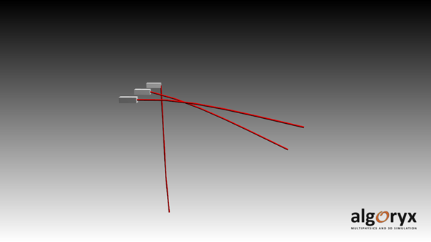
Fig. 15.15 Three links and wires where the wires has identical radius but the connection bend stiffness differs.
Another example where all wires has different radius and the links has identical default connection properties:
void createScene( agxSDK::Simulation* simulation )
{
  const agx::Real radius1 = 0.050;
  const agx::Real radius2 = 0.025;
  const agx::Real radius3 = 0.010;

  agxWire::WireRef wire1 = new agxWire::Wire( radius1, 2.0 );
  agxWire::LinkRef link1 = new agxWire::Link( createLink( simulation ) );

  agxWire::WireRef wire2 = new agxWire::Wire( radius2, 2.0 );
  agxWire::LinkRef link2 = new agxWire::Link( createLink( simulation ) );

  agxWire::WireRef wire3 = new agxWire::Wire( radius3, 2.0 );
  agxWire::LinkRef link3 = new agxWire::Link( createLink( simulation ) );

  // Before making any connections, set default bend stiffness.

  // Closest wire in the picture.
  link1->getDefaultConnectionProperties()->setBendStiffness( 1.0E10 );
  // Middle wire.
  link2->getDefaultConnectionProperties()->setBendStiffness( 1.0E10 );
  // Farthest wire.
  link3->getDefaultConnectionProperties()->setBendStiffness( 1.0E10 );

  link1->getRigidBody()->setPosition( 0, -1, 0 );
  link2->getRigidBody()->setPosition( 0,  0, 0 );
  link3->getRigidBody()->setPosition( 0,  1, 0 );

  simulation->add( new agx::LockJoint( link1->getRigidBody() ) );
  simulation->add( new agx::LockJoint( link2->getRigidBody() ) );
  simulation->add( new agx::LockJoint( link3->getRigidBody() ) );

  wire1->add( link1, agx::Vec3( 0.15, 0, 0 ) );
  wire1->add( new agxWire::FreeNode( 3, -1, 0 ) );

  wire2->add( link2, agx::Vec3( 0.15, 0, 0 ) );
  wire2->add( new agxWire::FreeNode( 3, 0, 0 ) );

  wire3->add( link3, agx::Vec3( 0.15, 0, 0 ) );
  wire3->add( new agxWire::FreeNode( 3, 1, 0 ) );

  simulation->add( wire1 );
  simulation->add( wire2 );
  simulation->add( wire3 );
}
Resulting in this steady state:
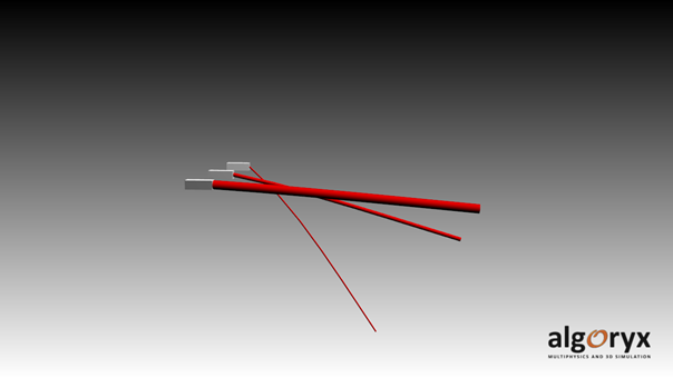
Fig. 15.16 Three links and wires where the connection bend stiffness is identical but the wires has different radii.
A trained eye can see that the relation between the radius and stiffness is proportional to r4.