22. AGX Tracks
A tracked vehicle is an object containing one or more tracks. Each track contains two or more wheels and an arbitrary number of treads.
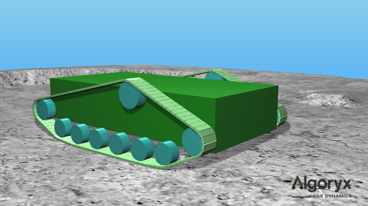
Fig. 22.1 Tracked vehicle with two tracks, each track has nine wheels and 100 treads.
22.1. agxVehicle::Wheel
Base class of an abstraction of a wheel of arbitrary geometry. An agxVehicle::Wheel is constructed
given radius, rigid body and a relative frame.
- Definition:
A wheel has a center, a radius and a rotation axis.
Since the given rigid body can be any user defined object, the relative frame defines the center and rotation axis of the wheel and is given in the frame of the wheel body.
The resulting frame should have the rotation axis about y and up axis along z.
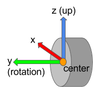
Fig. 22.2 Cylindrical wheel with wheel frame defining center position, rotation and up axes.
22.2. agxVehicle::TrackWheel
An agxVehicle::TrackWheel is an agxVehicle::Wheel and inherits the definitions of center,
radius and reference frame. The track wheel comes with a few more important features; model and property.
This means that each track wheel is of a certain model and contains a set of properties.
Model |
Description |
|---|---|
Sprocket |
Driving wheel - this wheel’s shaft is connected to the powerline/motor. Sprockets are normally geared where the treads wont slip while in good touch with the surface of the sprocket. |
Idler |
Geared, non-powered wheel. Similar surface properties as the sprocket but this model isn’t powered. |
Roller |
Intermediate track-return or road wheel. |
The properties associated to the track wheels are by default assigned given the model.
Property |
Description |
Model |
|---|---|---|
Merge nodes |
Treads/nodes are merged to the wheel when in contact, mimicking geared interaction (or infinite friction). |
Sprockets and idlers |
Split segments |
Splits merged segments of treads/nodes when in contact with wheels with this property. |
Optional |
Move nodes to rotation plane |
If enabled - when a node is merged to the wheel, move the node into the plane defined by the wheel center position and rotation axis. This will prevent the tracks from sliding of its path but all wheels with MERGE_NODES must be aligned. |
Optional |
Move nodes to wheel |
Similar to move nodes to rotation plane but with this property enabled the node will also be placed on the surface of the wheel. |
Optional |
Example of a cylindrical track wheel, trivially created with reference frame oriented with the rigid body. The wheel is attached in world with a hinge about the rotation axis and zero rotation axis offset:
const auto wheelRadius = 0.45;
const auto wheelHeight = 0.35;

agx::RigidBodyRef wheelRb = new agx::RigidBody( "wheelRb" );
wheelRb->add( new agxCollide::Geometry( new agxCollide::Cylinder( wheelRadius, wheelHeight ) ) );

agxVehicle::TrackWheelRef wheel = new agxVehicle::TrackWheel( agxVehicle::TrackWheel::SPROCKET,
                                                              wheelRadius,
                                                              wheelRb );
// Attaching the wheel with a hinge named "hinge" in world (nullptr) and
// 0.0 meters offset along the rotation axis.
auto hinge = wheel->attachHinge( "hinge", nullptr, 0.0 );
hinge->getMotor1D()->setEnable( true );
hinge->getMotor1D()->setSpeed( 1.0 );

simulation->add( wheelRb );
simulation->add( hinge );
It’s hard to create an example with a more complex setup with non-identity reference frame. To verify the
wheel frame, from case to case, render the frame using wheel->getTransform(), for example:
#include <agxRender/RenderSingleton.h>
...
  agxRender::debugRenderFrame( wheel->getTransform(), 0.25, agxRender::Color::Red() );
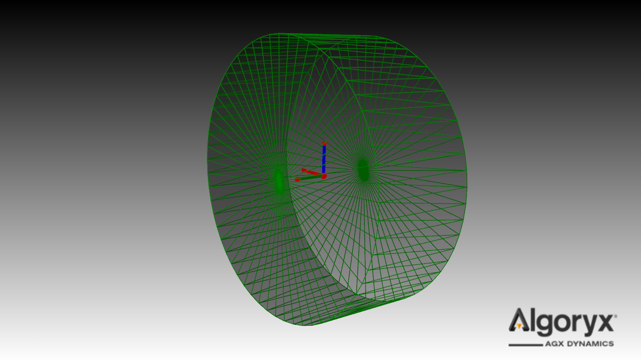
Fig. 22.3 Track wheel with radius 0.45 m and height 0.35 m. Hinged in world with hinge axis along the green (wheel) rotation axis.
22.3. agxVehicle::Track
Assembly object representing a continuous track with a given number of treads/nodes.
22.3.1. Initialization
An agxVehicle::Track is instantiated given desired number of nodes and width and thickness of each node. The width and thickness are both reference values - i.e., not actual, meaning the geometry may have different dimensions. The thickness value is used place the nodes as close as possible to the surface of the wheels.
The ‘’unknown’’ parameter is the length of each node. The length of the nodes is calculated during initialization to properly fit the track round the wheels.
22.3.1.1. Routing with wheels
Routing of the tracks is made by adding wheels to the track. Given number of nodes in the track, thickness of the nodes and wheel configuration (transform and radius), the track routing algorithm will calculate the length each node should have for the track to go outside all wheels.
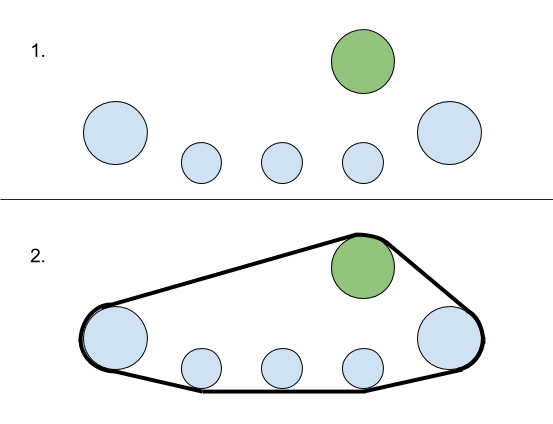
Fig. 22.4 Initial wheel configuration (1) and resulting track route (2).
Note
It doesn’t matter in which order the wheels has been added to the tracks.
Note
It’s currently only possible to initialize the tracks in a convex shape.
Small example given an array of wheel bodies that has been positioned and an array of wheel radii. The first wheel will be set to be the sprocket, all others are rollers:
agxVehicle::TrackRef track = new agxVehicle::Track( numNodes, width, thickness );
for ( agx::UInt i = 0; i < wheelBodies.size(); ++i ) {
  agxVehicle::TrackWheelRef wheel = new agxVehicle::TrackWheel( i == 0 ?
                                                                  agxVehicle::TrackWheel::SPROCKET :
                                                                  agxVehicle::TrackWheel::ROLLER,
                                                                wheelRadius[ i ],
                                                                wheelBodies[ i ] );
  track->add( wheel );
}

// The track will be initialized when added to a simulation if
// agxVehicle::Track::initialize hasn't been called explicitly.
simulation->add( track );
22.3.1.2. Reference wheel
The reference wheel is used as reference during initialization of the tracks. The nodes will be positioned in the plane defined by the reference wheel position and rotation axis.
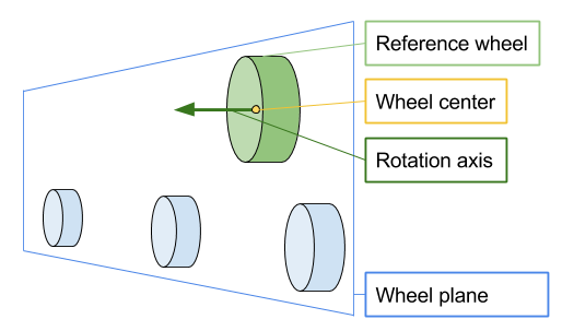
Fig. 22.5 Plane defined by the reference wheel center position and rotation axis.
The reference wheel is defined to be the first sprocket wheel (if any), otherwise first idler wheel (if any), otherwise the first roller.
- Definition:
The reference wheel is the first sprocket wheel added to a track.
22.3.1.3. Initial tension
If the track finds a solution to the initial configuration and the actual geometry of the nodes matches the input thickness - the tension on the tracks will be close to zero. If the vehicle/object doesn’t have e.g., a tensioner, it’s possible to initialize the tracks with tension.
The initial tension parameter is a distance (not a force). It’s not a force because it’s hard to find an initial state where the actual tension in the track is the given force - without simulating the track for some time with the given geometries of the nodes and wheels. The given distance (if positive) is how much closer each node should be initialized to each other. The given distance (if negative) is how much further away each node should be initialized from each other.
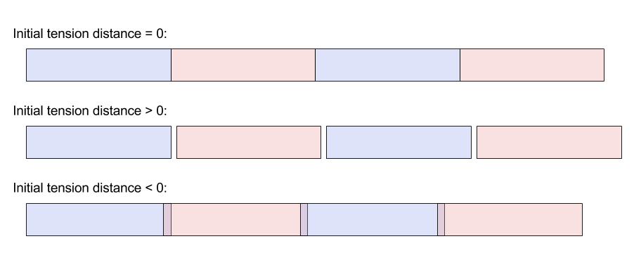
Fig. 22.6 Initial tension distance when zero (no tension), positive (initially stretched) and negative (initially compressed).
22.3.1.4. Node geometry
As for the wheels, the geometry of the nodes are completely arbitrary. Box is used by default.
Create geometry callbacks are fired when the node has been positioned. The z-axis of the node body is pointing in the direction of the track and the model center must be at the begin position of the node. The default ‘createGeometryBox’’ function looks like this:
void createGeometryBox( const TrackNode& node )
{
  // Node half extents = (0.5 * thickness, 0.5 * width, 0.5 * length)
  agxCollide::BoxRef box = new agxCollide::Box( node.getHalfExtents() );
  agxCollide::GeometryRef geometry = new agxCollide::Geometry( box );
  // Model center is begin of node, translate geometry forward 0.5 * length (along z).
  const auto transform = agx::AffineMatrix4x4::translate( 0,
                                                          0,
                                                          node.getHalfExtents().z() );
  geometry->setLocalTransform( transform );
  node.getRigidBody()->add( geometry );
}
Adding the track to the simulation without calling initialize beforehand is equivalent to call initialize given ‘’createGeometryBox’’ and then adding the track to the simulation:
// Default initialization...
simulation->add( track );
// ...is equivalent to:
anotherTrack->initialize( agxVehicle::utils::createGeometryBox );
simulation->add( anotherTrack );
Example of two tracks where one is initialized with several sphere shapes as geometry (initialize function) and the other with capsules (interface):
class NodeCapsuleInitializer : public agxVehicle::TrackNodeOnInitializeCallback
{
  public:
    NodeCapsuleInitializer() {}

    virtual void onInitialize( const agxVehicle::TrackNode& node ) override
    {
      agxCollide::CapsuleRef capsule = new agxCollide::Capsule( 0.5 * node.getWidth(),
                                                                node.getLength() );
      node.getRigidBody()->add( new agxCollide::Geometry( capsule ),
                                agx::AffineMatrix4x4::rotate( agx::Vec3::Y_AXIS(),
                                                              agx::Vec3::Z_AXIS() ) *
                                agx::AffineMatrix4x4::translate( 0, 0, 0.5 * node.getLength() ) );
    }

  protected:
    virtual ~NodeCapsuleInitializer() {}
};

const agx::Real sphereRadius = 0.1;
// Creates track with five wheels, 60 nodes and width = thickness = 2.0 * sphereRadius.
agxVehicle::TrackRef sphereTrack = createTrack( 2.0 * sphereRadius, 2.0 * sphereRadius );
agxVehicle::TrackRef capsuleTrack = createTrack( 2.0 * sphereRadius, 2.0 * sphereRadius );

sphereTrack->setPosition( 0, -1, 0 );
capsuleTrack->setPosition( 0, 1, 0 );

// Initializing the sphere track with several spheres as geometry.
sphereTrack->initialize( [sphereRadius]( const agxVehicle::TrackNode& node )
{
  const auto offset = 0.5 * sphereRadius;

  const auto numSpheres = std::max( agx::UInt( node.getLength() / offset +
                                               agx::Real( 0.5 ) ),
                                    agx::UInt( 1 ) );
  const auto dl = node.getLength() / agx::Real( numSpheres );
  agxCollide::GeometryRef geometry = new agxCollide::Geometry();
  auto pos = agx::Vec3( 0, 0, 0 );
  auto dir = agx::Vec3::Z_AXIS();
  for ( agx::UInt i = 0; i < numSpheres; ++i ) {
    geometry->add( new agxCollide::Sphere( sphereRadius ),
                   agx::AffineMatrix4x4::translate( pos ) );
    pos += dl * dir;
  }

  node.getRigidBody()->add( geometry );
} );

// Initializing the capsule track with one capsule per node.
capsuleTrack->initialize( new NodeCapsuleInitializer() );

simulation->add( sphereTrack );
simulation->add( capsuleTrack );
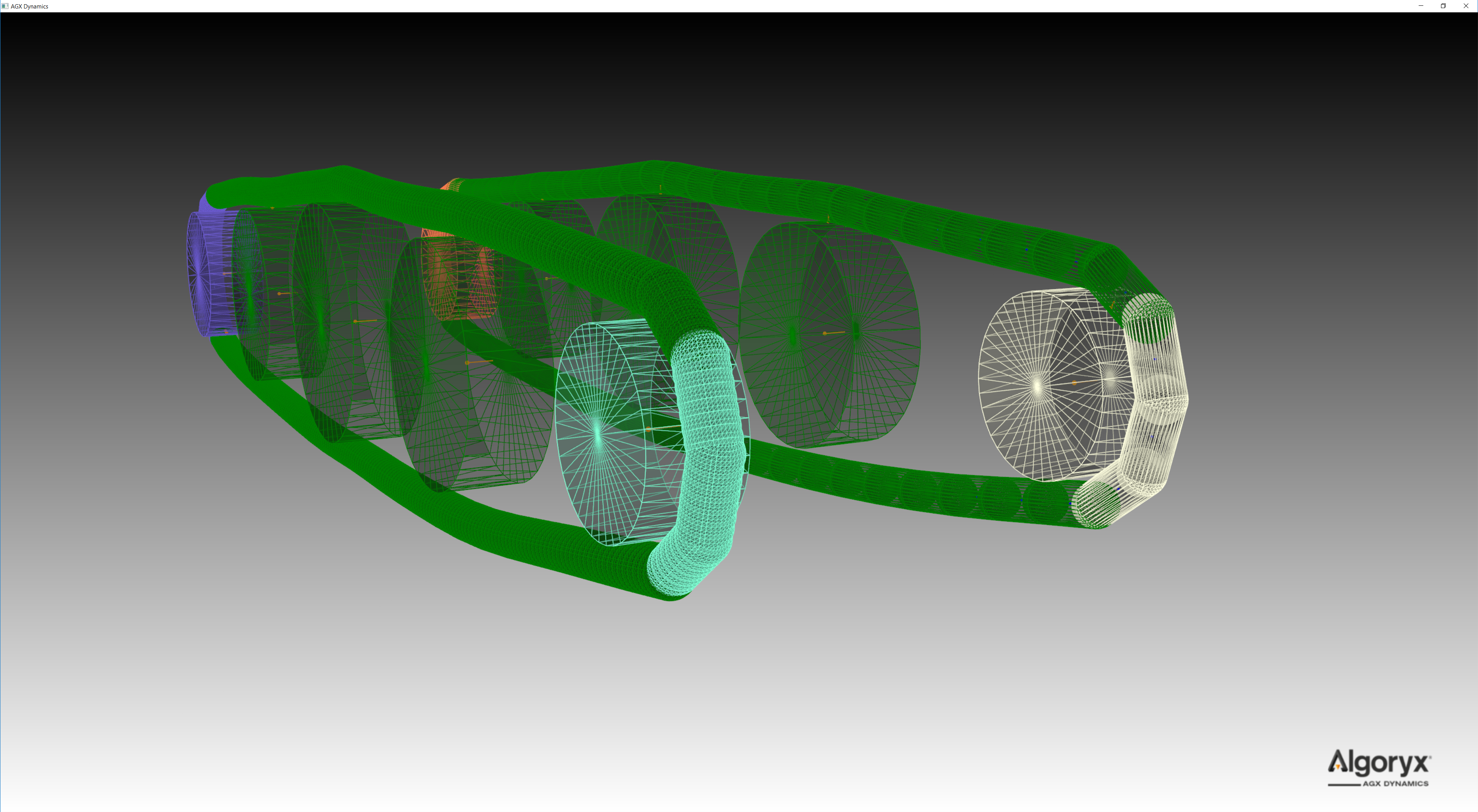
Fig. 22.7 Two tracks initialized with different geometries. Several spheres per node (left) and one capsule per node (right).
Each node doesn’t have to have identical shape/geometry. This example is from tutorial_trackedVehicle.cpp:buildTutorial2 where every fourth node is thicker than the three before:
// Two, different thickness values along the track. Every forth node is thicker than the three before.
const agx::Real defaultThickness = 0.05;
const agx::Real thickerThickness = 0.09;

agxVehicle::TrackRef track = new agxVehicle::Track( 120, 0.4, defaultThickness, 0.0 );
track->add( createTrackWheel( agxVehicle::TrackWheel::Model::SPROCKET, 0.5, 0.3, agx::Vec3( 0, 0, 0 ) ) );
track->add( createTrackWheel( agxVehicle::TrackWheel::Model::ROLLER, 0.6, 0.3, agx::Vec3( 2, 0, 0 ) ) );
track->add( createTrackWheel( agxVehicle::TrackWheel::Model::ROLLER, 0.7, 0.3, agx::Vec3( 4, 0, 0 ) ) );
track->add( createTrackWheel( agxVehicle::TrackWheel::Model::ROLLER, 0.6, 0.3, agx::Vec3( 6, 0, 0 ) ) );
track->add( createTrackWheel( agxVehicle::TrackWheel::Model::IDLER, 0.4, 0.3, agx::Vec3( 8, 0, 0 ) ) );

// Initialization callback when the segmentation of the track has been made.
// When a callback is given to 'initialize' it's up to this callback to assign
// geometries/shapes to the nodes. Note that the track has calculated a length
// of the nodes that has to be taken into account.
agx::UInt counter = 0;
track->initialize( [&]( const agxVehicle::TrackNode& node )
{
  agx::Real heightOffset = 0.0;
  agx::Real thickness = defaultThickness;
  // For every fourth node we add a thicker box.
  if ( ( counter++ % 4 ) == 0 ) {
    thickness = thickerThickness;
    heightOffset = -0.5 * ( thickerThickness - defaultThickness );
  }
  node.getRigidBody()->add( new agxCollide::Geometry( new agxCollide::Box( 0.5 * thickness,
                                                                           0.25,
                                                                           0.5 * node.getLength() ) ),
                            agx::AffineMatrix4x4::translate( heightOffset, 0, node.getHalfExtents().z() ) );
} );
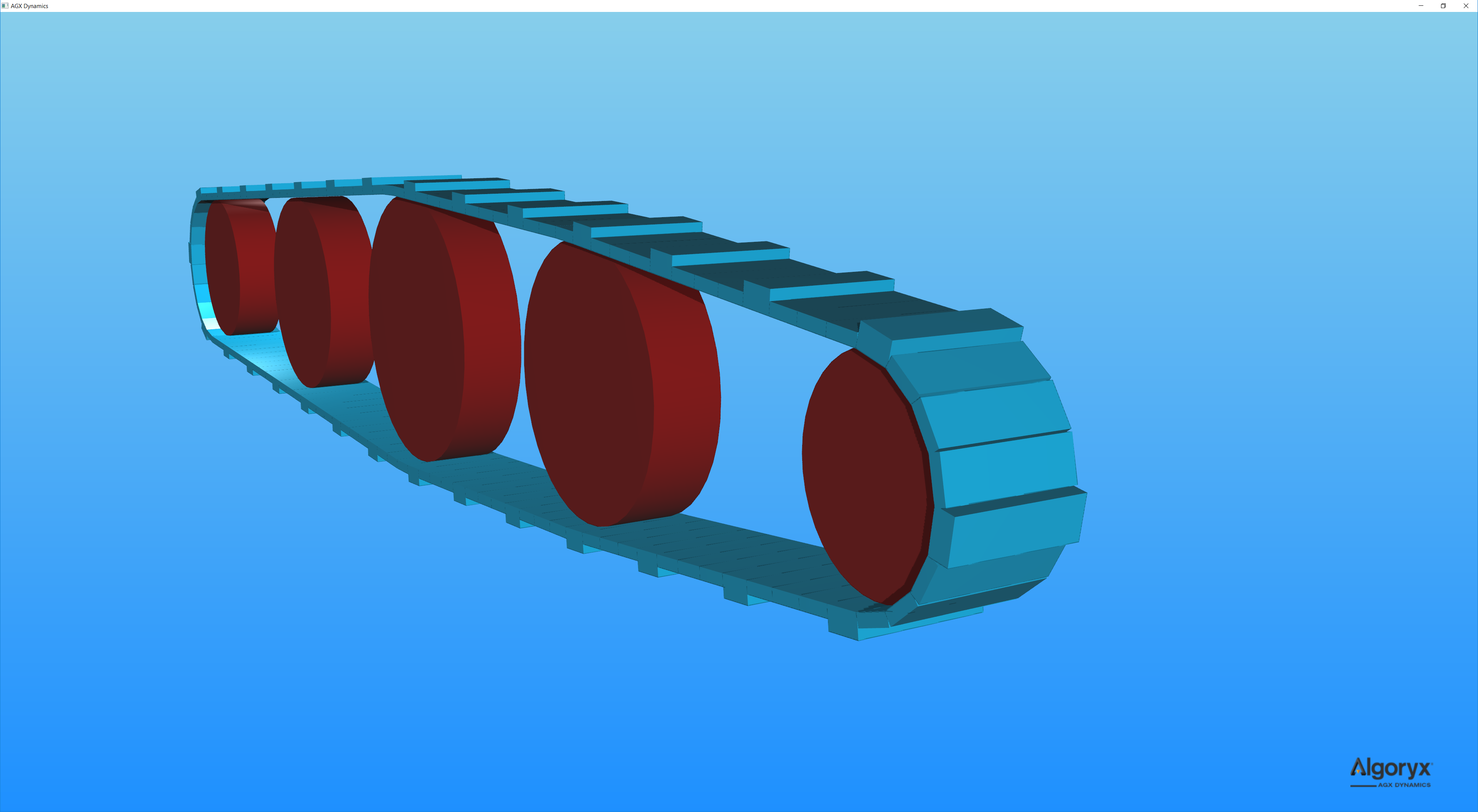
Fig. 22.8 Track initialized with different shapes/geometries along the track. Every fourth geometry is larger than the three before.
22.3.2. Accessing the nodes in a track
When the track has been initialized it’s possible to iterate the nodes in the track in a few different ways:
for ( agx::UInt i = 0; i < track->getNumNodes(); ++i ) {
  agxVehicle::TrackNode* node = track->getNode( i );
  ...
}

for ( agxVehicle::TrackNode* node : track->nodes() ) {
  ...
}
Since the track is continuous, i.e., no actual start or end, the use of ranges is more convenient:
// Iterating all nodes.
for ( agxVehicle::TrackNode* node : track->nodes( { 0u, track->getNumNodes() } ) ) {
  ...
}

// Iterating segments.
const auto numNodesPerSegment = 5u;
for ( agx::UInt nodeIndex = 0; nodeIndex < track->getNumNodes(); nodeIndex += numNodesPerSegment ) {
  agxVehicle::Track::NodeRange range{ track->getIterator( nodeIndex ),
                                      track->getIterator( nodeIndex + numNodesPerSegment ) };
  for ( agxVehicle::TrackNode* node : range ) {
    // Do stuff with the node in range.
  }
}

// Since continuous, this is valid to iterate six nodes in a track with 100 nodes.
auto range = agxVehicle::Track::NodeRange{ track->getIterator( 1234u ),
                                           track->getIterator( 1234u + 6u ) };
for ( agxVehicle::TrackNode* node : range ) {
  std::cout << node->getIndex() << std::endl;
}

// Prints:
//   34
//   35
//   36
//   37
//   38
//   39
22.3.3. Simulation parameters
Given an initialized track, there are some special handling regarding the interaction between the track and the wheels:
Sprockets: Instead of frictional contacts, nodes will merge with the sprocket - mimicking infinite friction or geared wheel versus track.
Idlers: Default behavior is identical to the sprockets.
Rollers: Frictional contacts. If computational performance is important, make sure the contact material between the rollers and the track nodes has been properly tweaked. E.g, for direct friction models - high surface viscosity.
22.3.3.1. Contact materials and friction models
The default friction model and contact material normally isn’t suitable for simulating track versus ground interactions. Mainly because the friction box is oriented with the world frame and we’re interested in separating the contact parameters along the track and orthogonal to the track.
See Section 11.16.3.4 for oriented friction models and Section 11.16.3.5 in particular for best performance.
Normally a significant amount of nodes are in contact with the ground/floor/other objects, resulting in many contact points. For best numerical and behavioral performance:
Use a direct friction model solve type (
agx::FrictionModel::DIRECToragx::FrictionModel::DIRECT_AND_ITERATIVE).Use
agx::ConstantNormalForceOrientedBoxFrictionModelif possible with an estimate of the normal force for each contact point. EnablescaleWithDepthif the system is within bounds, performance vise.Set the surface viscosity as high as possible but low enough for the object to not slide with constant speed.
Use different friction coefficients and surface viscosity along and orthogonal to the tracks – usually lower friction and higher viscosity orthogonal to the tracks.
Set restitution to zero for better stability and continuous contacts.
Example from tutorial_trackedVehicle.cpp (vehicle shown in Fig. 22.1):
// Setting up materials.
const agx::Real trackDensity                    = 2000.0;
const agx::Vec2 trackGroundFrictionCoefficients = agx::Vec2( 1000.0, 10 );
const agx::Vec2 trackGroundSurfaceViscosity     = agx::Vec2( 1.0E-7, 8.0E-6 );
const agx::Real trackWheelFrictionCoefficient   = 1.0;
const agx::Real trackWheelSurfaceViscosity      = 1.0E-5;
Note the differences in friction coefficients and viscosity. These has to be chosen to match the performance criterion, stability and behavior. Further:
agx::MaterialRef groundMaterial = new agx::Material( "groundMaterial" );
agx::MaterialRef trackMaterial  = new agx::Material( "trackMaterial" );
agx::MaterialRef wheelMaterial  = new agx::Material( "wheelMaterial" );

trackMaterial->getBulkMaterial()->setDensity( trackDensity );

ground->setMaterial( groundMaterial );

trackedVehicle->getRightTrack()->setMaterial( trackMaterial );
for ( const auto wheel : trackedVehicle->getRightTrack()->getWheels() )
  agxUtil::setBodyMaterial( wheel->getRigidBody(), wheelMaterial );

trackedVehicle->getLeftTrack()->setMaterial( trackMaterial );
for ( const auto wheel : trackedVehicle->getLeftTrack()->getWheels() )
  agxUtil::setBodyMaterial( wheel->getRigidBody(), wheelMaterial );
Note that we’re separating ground, wheel and track materials. Normally it’s enough to use the default friction model for the contacts between the track nodes and the wheels, but if the wheels doesn’t respond enough to the friction, a simplified direct friction model can be used:
// Contact material between track nodes and the wheels.
auto trackWheelContactMaterial = simulation->getMaterialManager()->getOrCreateContactMaterial( trackMaterial,
                                                                                               wheelMaterial );
// Slightly simplified friction model between the wheels and the track
// where we estimate the normal force constant @ ten times the mass of
// the chassis. Solved direct.
auto trackFmConstantNormalForce = 10.0 * trackedVehicle->getChassis()->getMassProperties()->getMass();
auto trackWheelFrictionModel = new agx::ConstantNormalForceOrientedBoxFrictionModel( trackFmConstantNormalForce,
                                                                                     trackedVehicle->getChassis()->getFrame(),
                                                                                     agx::Vec3::X_AXIS(),
                                                                                     agx::FrictionModel::DIRECT );
trackWheelContactMaterial->setFrictionModel( trackWheelFrictionModel );
// Let the friction coefficient be high and "ease up" the friction constraints
// by using high surface viscosity. Friction properties doesn't affect the
// sprockets or idlers since the nodes will merge to them, simulating infinite
// stick friction against those geared wheel types.
trackWheelContactMaterial->setFrictionCoefficient( trackWheelFrictionCoefficient );
trackWheelContactMaterial->setSurfaceViscosity( trackWheelSurfaceViscosity );
trackWheelContactMaterial->setRestitution( 0.0 );
The contact material between the track nodes and ground is similar but here we include primary and secondary parameters:
// Contact material between track nodes and the ground.
auto trackGroundContactMaterial = simulation->getMaterialManager()->getOrCreateContactMaterial( trackMaterial, groundMaterial );
// Similar friction model as between the tracks and the wheels but here, between
// the tracks and ground it's important that the friction box is oriented with
// the tracked vehicle. We want the traction along the tracks to be very high
// and the transverse traction slightly lower to make it possible to turn smoothly.
// This friction model will scale the maximum friction force with the contact point.
auto trackGroundFrictionModel = new agx::ConstantNormalForceOrientedBoxFrictionModel( trackFmConstantNormalForce,
                                                                                      trackedVehicle->getChassis()->getFrame(),
                                                                                      agx::Vec3::X_AXIS(),
                                                                                      agx::FrictionModel::DIRECT,
                                                                                      true );
trackGroundContactMaterial->setFrictionModel( trackGroundFrictionModel );
trackGroundContactMaterial->setFrictionCoefficient( trackGroundFrictionCoefficients.x(),
                                                    agx::ContactMaterial::PRIMARY_DIRECTION );
trackGroundContactMaterial->setFrictionCoefficient( trackGroundFrictionCoefficients.y(),
                                                    agx::ContactMaterial::SECONDARY_DIRECTION );
trackGroundContactMaterial->setSurfaceViscosity( trackGroundSurfaceViscosity.x(),
                                                 agx::ContactMaterial::PRIMARY_DIRECTION );
trackGroundContactMaterial->setSurfaceViscosity( trackGroundSurfaceViscosity.y(),
                                                 agx::ContactMaterial::SECONDARY_DIRECTION );
trackGroundContactMaterial->setRestitution( 0.0 );
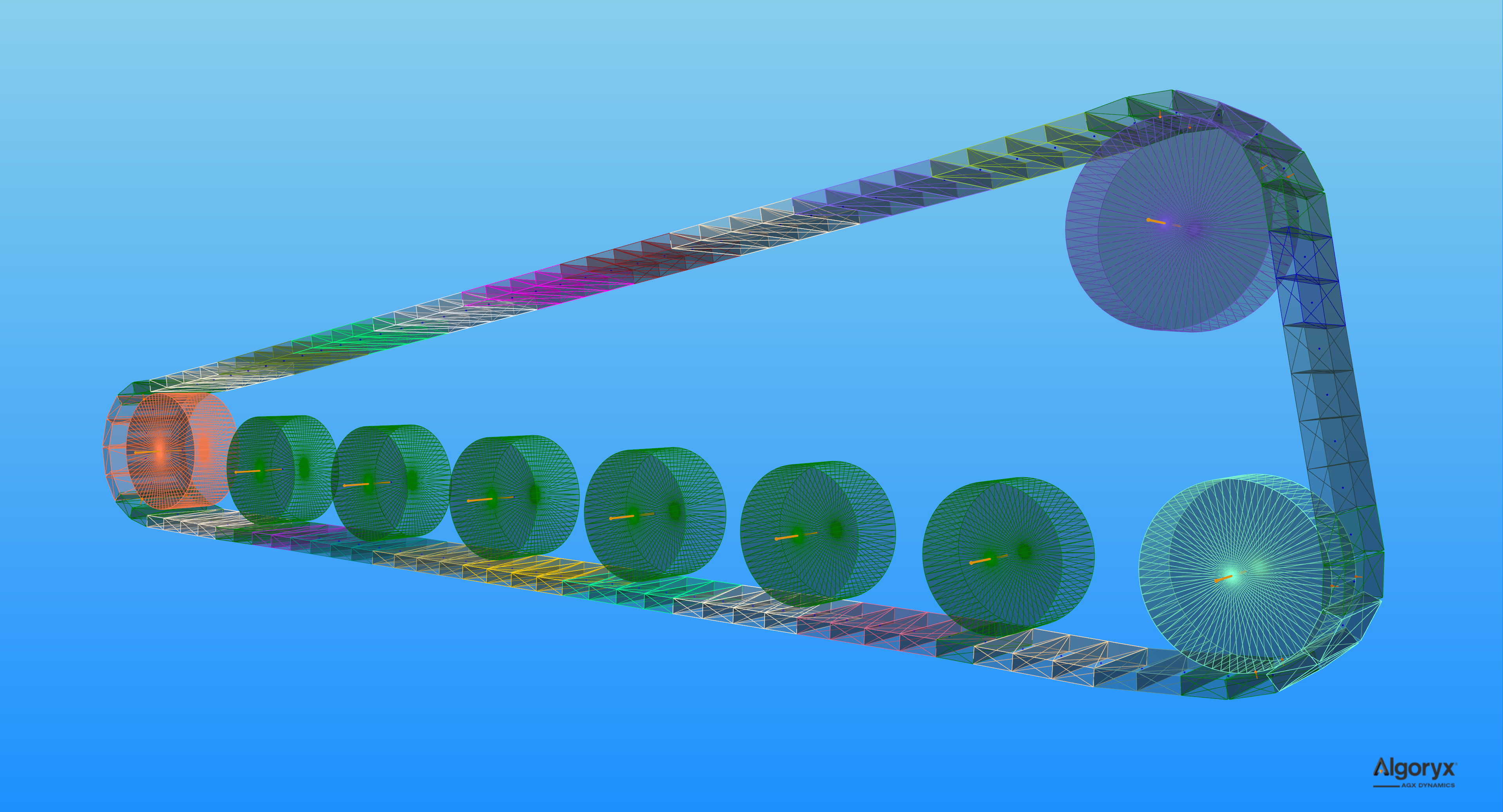
22.3.3.2. Merging segments
For performance reasons, it’s possible to enable merging of nodes to segments along the track. The result can be seen in Fig. 22.2 where each segment has a different color. When the nodes are merged together several bodies and constraints aren’t added to the solver (reducing the size of the matrix) and it’s possible to perform contact reduction over the whole segment.
To enable merge (disabled by default):
auto mergeProperties = track->getInternalMergeProperties();
// Default: false
mergeProperties->setEnableMerge( true );
By default (when enabled), three nodes will merge together to a segment. To change the number of nodes to merge simply:
// Setting the number of nodes per segment to 6 (default 3).
mergeProperties->setNumNodesPerMergeSegment( 6u );
Contact reduction is by default minimal which means some contacts will be removed. The other options are none for no contact reduction, moderate for more contacts to be neglected and aggressive for the most intrusive reduction:
// Default: agxVehicle::TrackInternalMergeProperties::MINIMAL (bin resolution 3)
mergeProperties->setContactReduction( agxVehicle::TrackInternalMergeProperties::MODERATE );
The nodes must be aligned to be merged to avoid curvatures to build along the track. The nodes are constrained together with hinges and by default (when merge is enabled) the lock in the hinge is used to force the nodes to their straight/resting position. It’s possible to toggle this feature and set compliance and damping of the lock:
// Default: true
mergeProperties->setEnableLockToReachMergeCondition( true );
// Default: 1.0E-11 (very strong)
mergeProperties->setLockToReachMergeConditionCompliance( 1.0E-6 );
// Default: 3.0 / 60.0
mergeProperties->setLockToReachMergeConditionDamping( 6.0 * timeStep );
// Maximum angle > 0 (in radians) when the nodes may merge.
// Default: 1.0E-5
mergeProperties->setMaxAngleMergeCondition( 6.0E-5 );
22.3.3.3. Track properties
All parameters and features implemented in the tracks model are exposed in the agxVehicle::TrackProperties
object. All track instances has an instance of this object and it’s possible for several track instances to share
a single instance of this object, e.g.:
auto globalProperties = track1->getProperties();
track2->setProperties( globalProperties );
track3->setProperties( globalProperties );

agxVehicle::TrackPropertiesRef otherProperties = new agxVehicle::TrackProperties()
track4->setProperties( otherProperties );
track5->setProperties( otherProperties );
There are many parameters in the track properties, some more important than others. This table, under ‘’Property’’
is the accessor and mutator name – just add get or set and remove any spaces. E.g., Hinge Compliance is
properties->setHingeCompliance( c ) and auto c = properties->getHingeCompliance():
Property |
Description |
Default value |
|---|---|---|
Hinge Compliance |
Compliance of the hinge between track nodes. It’s possible to specify compliance for each separate degree of freedom in the hinge, all translational or rotational. |
1.0E-10 |
Hinge Damping |
Damping of the hinge between track nodes. It’s possible to specify damping for each separate degree of freedom in the hinge, all translational or rotational. |
2.0 / 60.0 |
Min Stabilizing Hinge Normal Force |
Minimum value of the normal force (the hinge force along the track) used in “internal” friction calculations. I.e., when the track is compressed, this value is used with the friction coefficient as a minimum stabilizing compliance. If this value is negative there will be stabilization when the track is compressed. |
100 |
Stabilizing Hinge Friction Parameter |
Friction parameter of the internal friction in the node hinges. This parameter scales the normal force in the hinge. |
1 |
Enable Hinge Range |
Enable/disable hinge range between track nodes to define how the track may bend. |
true |
Hinge Range Range |
The range (in radians) defining allowed relative angle between track nodes. |
\(-270 \leq \alpha \leq 20\) degrees. |
Enable On Initialize Merge Nodes To Wheels |
When the track has been initialized some nodes are in contact with the wheels. If this flag is true the interacting nodes will be merged to the wheel directly after initialize, if false the nodes will be merged during the first (or later) time step. |
false |
Enable On Initialize Transform Nodes To Wheels |
True to position/transform the track nodes to the surface of the wheels after the track has been initialized. When false, the routing algorithm positions are used. |
true |
Transform Nodes To Wheels Overlap |
When the nodes are transformed to the wheels, this is the final target overlap. |
1.0E-3 |
Nodes To Wheels Merge Threshold |
Threshold when to merge a node to a wheel. Given a reference direction in the track, this value is the projection of the deviation (from the reference direction) of the node direction onto the wheel radial direction vector. I.e., when the projection is negative the node can be considered “wrapped” on the wheel. |
-0.1 |
Nodes To Wheels Split Threshold |
Threshold when to split a node from a wheel. Given a reference direction in the track, this value is the projection of the deviation (from the reference direction) of the node direction onto the wheel radial direction vector. I.e., when the projection is negative the node can be considered “wrapped” on the wheel. |
-0.05 |
Num Nodes Included In Average Direction |
Average direction of non-merged nodes entering or exiting a wheel is used as reference direction to split of a merged node. This is the number of nodes to include into this average direction. |
3 |
22.3.3.3.1. Internal friction in the hinges
Internal friction in the hinges is used to stabilize the nodes in the track during high tension. The default friction coefficient (Stabilizing Hinge Friction Parameter) is relatively high and could work by default if the track is relatively large (sitting on a large tracked vehicle for example).
When the friction parameter is too low, the tracks will become unstable.
When the friction parameter is too high, the tracks will seem un-bendable, penetrating the wheels and/or the wheels aren’t able to drive the track.
For example the tracked vehicle in tutorial_trackedVehicle.cpp (Fig. 22.1):
track->getProperties()->setStabilizingHingeFrictionParameter( 1.5 );
And to simulate a much smaller (thinner where the node mass is significantly smaller) track, in the same tutorial file, simulating a conveyor belt:
conveyor->getProperties()->setStabilizingHingeFrictionParameter( 4.0E-3 );
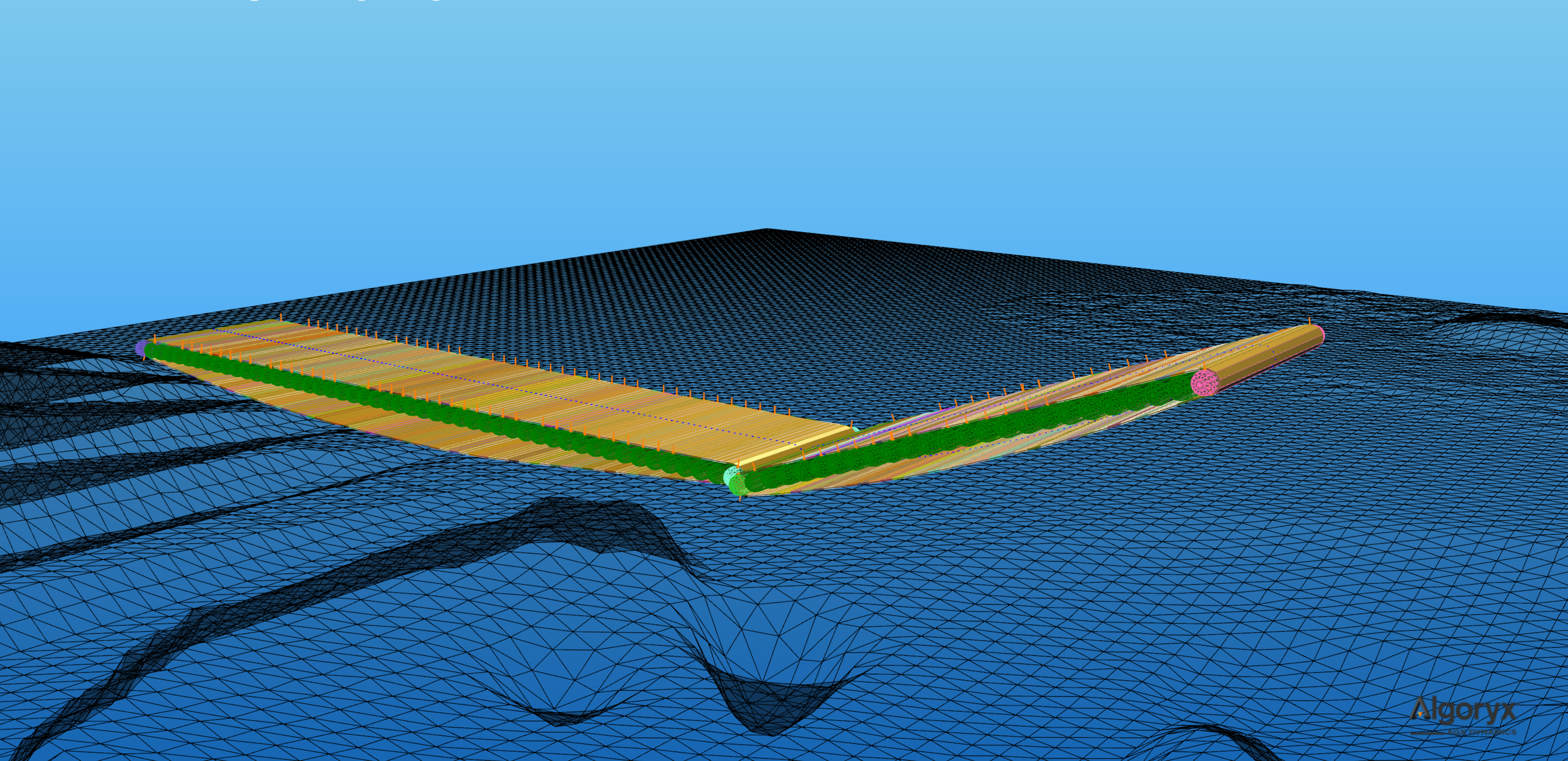
Fig. 22.9 Simulating conveyor belt using agxVehicle::Track where each roller is a wheel.