30. Strong interaction
Strong interaction is a concept in AGX Dynamics enabling the possibility to write data in the mass matrix part of the system matrix.
The equation system (symmetric version):
The general strong interaction interface enables the user to write the following equation system:
Where \(A\) is symmetric and \(a\) is any value.
30.1. Strong interaction constraint
To validate this feature, it is possible to create an instance of agx::StrongInteractionConstraint based on any of our ordinary (hinge, prismatic, lock joint etc.) constraints. This will mimic the functionality of the ordinary constraint.
The strong interaction constraint will write the constraint data in \(A\) and \(a\) instead of \(G\). The system for the direct solver to solve then becomes:
Where, for two rigid bodies, \(G^TG\) is a 12x12 (symmetric) matrix. I.e., two 6x6 blocks (for rigid body 1 and 2) in the diagonal and one additional 6x6 block, off diagonal.
The code snipped below illustrates the setup:
auto frame1 = new agx::Frame();
auto frame2 = new agx::Frame();
auto lock = new agx::LockJoint(body1, frame1, body2, frame2);
auto lockStrong = new agx::StrongInteractionConstraint( lock );
simulation->add( lockStrong );
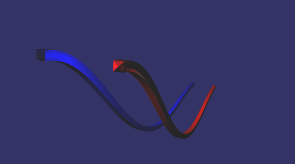
Fig. 30.1 Segmented beams. Blue using lock joints and red the strong interaction constraint concept. The trajectories are close to identical.
30.2. Added mass interaction
The added mass interaction, agx::AddedMassInteraction, is the strong interaction defined between one or two rigid bodies. The object contains three matrix blocks (each 6x6) – one for the first rigid body, another one for the second rigid body and a third which is the off diagonal block.
30.2.1. Example
Below is an example that creates an interaction between ship1 and ship2, assigns the data and verifies so that the constructor arguments are one to one with the API:
// Create added mass interaction between ship 1 and ship 2.
agx::AddedMassInteractionRef addedMassInteraction = new agx::AddedMassInteraction( ship1, ship2 );

// Enable/disable (enabled by default).
addedMassInteraction->setEnable( false );
addedMassInteraction->setEnable( true );

// Add to a simulation.
simulation->add( addedMassInteraction );

auto blockAssign = []( const agx::Real* data, agx::AddedMassInteraction::Matrix6x6& block )
{
  for ( agx::UInt i = 0; i < 6; ++i )
    for ( agx::UInt j = 0; j < 6; ++j )
      block[ i ][ j ] = data[ 6 * i + j ];
};

// Assign diagonal block for ship1.
blockAssign( ship1AddedMassData, addedMassInteraction->getRigidBody1Storage()->getBlock() );
// Diagonal block for ship2.
blockAssign( ship2AddedMassData, addedMassInteraction->getRigidBody2Storage()->getBlock() );
// Off diagonal block, default assumed to be given in ship1 center of gravity frame.
blockAssign( offDiagonalData, addedMassInteraction->getOffDiagonalBlock() );

agxAssert( addedMassInteraction->getRigidBody1() == ship1 );
agxAssert( addedMassInteraction->getRigidBody2() == ship2 );
agxAssert( addedMassInteraction->getRigidBody1() ==
          addedMassInteraction->getRigidBody1Storage()->getRigidBody() );
agxAssert( addedMassInteraction->getRigidBody2() ==
          addedMassInteraction->getRigidBody2Storage()->getRigidBody() );
30.2.2. Coordinate systems
Coordinate systems of the three blocks are currently assumed to be:
Rigid body 1 block in rigid body 1 local center of gravity frame
Rigid body 2 block in rigid body 2 local center of gravity frame
Off-diagonal block in rigid body 1 local center of gravity frame
This is assumptions by the default implementation. The user may change this behavior by implementing the transformations themselves (see MatrixTransformer).
What is well defined for this interaction to be part of a whole system is that the output of the added mass interaction must be of the form such that the velocities are given in the world coordinate frame.
30.2.3. General transformations
In AGX Dynamics, rotation matrices of a rigid body transforms from a local to the world coordinate system. The transpose of that rotation matrix transforms from world to local.
const Matrix3x3 R  = Matrix3x3( rb->getCmRotation() );
const Matrix3x3 RT = R.transpose();
Consider an equation system with mass matrices and velocities given in local center of gravity frame:
From the direct solver point of view, the velocities has to be given in world coordinate frame. In order to get the velocities in world and to transform \({M}'\) to the world coordinate system we do the following (considering first block row):
We transform it to the world coordinate system by left multiplying with \({R^T_1}'\)
The corresponding matrix form with velocities in world then becomes:
This is how we transform our center of gravity mass matrices in the solver.
30.2.4. Off diagonal block
One very important aspect of the handling of these strong interaction mass blocks, is that the ordering of the global mass matrix is out of the control for any added mass interaction. This side effect is handled by the internal implementation but will become an issue whenever a custom Matrix transformer is used and hence need to be handled explicitly.
The mass matrix and velocities given N bodies where body i and body j interacts and has an off diagonal block allocated:
Following the same procedure as in General transformations we get:
Where \(R_x^T\) takes \({A}'_{ji} \) on the right because the off diagonal block is located at column index \(i\) (and will be multiplied with \(v_i\)).
The default implementation assumes \(R_x^T=R_{rb1}^T\), where \(rb1\) is the first rigid body passed to the agx::AddedMassInteraction object.
The tricky part is that we can’t assume body \(i\) and body \(j\) in the matrix maps \(rb_1\) and \(rb_2\) in the added mass interaction. The order can change between time steps! I.e., one time step body \(i\) is \(rb_1\) but the next time step body \(i\) could be \(rb_2\).
Given from the solver:
Body i.
Block row index of body i, i.e., i as a number.
Body j.
Block row index of body j, i.e., j as a number.
Hence the added mass interaction has to manually map its bodies to ones sent from the solver.
30.2.5. Matrix transformer
Because of the confusions around transforming the matrices, it’s possible to override the default behavior by implementing the transformation part on the user side.
addedMassInteraction->setMatrixTransformer( new MyMatrixTransformer() );
Where MyMatrixTransformer implements the method transform:
void MyMatrixTransformer::transform( const agx::AddedMassInteraction::RigidBodyStorage* rb1Storage,
                                    const agx::UInt rb1BlockRow,
                                    const agx::AddedMassInteraction::RigidBodyStorage* rb2Storage,
                                    const agx::UInt rb2BlockRow,
                                    const agx::AddedMassInteraction::Matrix6x6& offDiagonalBlock,
                                    agx::AddedMassInteraction::MatrixTransformer::Result& result ) const
{
  // From world to center of gravity frame.
  const agx::Matrix3x3 rb1R  = rb1Storage->getRigidBody() != 0L ?
                                agx::Matrix3x3( rb1Storage->getRigidBody()->getCmRotation() ) :
                                agx::Matrix3x3();
  const agx::Matrix3x3 rb2R  = rb2Storage->getRigidBody() != 0L ?
                                agx::Matrix3x3( rb2Storage->getRigidBody()->getCmRotation() ) :
                                agx::Matrix3x3();
  // From center of gravity frame to world.
  const agx::Matrix3x3 rb1RT = rb1R.transpose();
  const agx::Matrix3x3 rb2RT = rb2R.transpose();

  // Given A_ij are 3x3 blocks, transform( RT, R ) performs:
  //   RT A_00 R     RT A_01 R
  //   RT A_10 R     RT A_11 R
  result.rb1DiagonalBlock = rb1Storage->getBlock().transform( rb1RT, rb1R );
  result.rb2DiagonalBlock = rb2Storage->getBlock().transform( rb2RT, rb2R );

  // Assuming offDiagonalBlock is given in rb1Storage coordinate system!
  // <-> first argument to transform is rb1RT.

  // rb1 block is above rb2 in the matrix, transform from right should be to rb1.
  if ( rb1BlockRow < rb2BlockRow )
    result.offDiagonalBlock = offDiagonalBlock.transform( rb1RT, rb1R );
  // rb2 block is above rb2 in the matrix, transform from right should be to rb2.
  else
    result.offDiagonalBlock = offDiagonalBlock.transform( rb1RT, rb2R );
}
Worth noticing is the logic round rb1BlockRow and rb2BlockRow to choose which matrix to multiply from the right.
If MyMatrixTransformer was used in the first example, we could assume that rb1Storage contains the data for ship1 and rb2Storage the data for ship2.
I.e., these aren’t changed when the solver changes the order – it’s handled by the implementation that calls transform!
Overriding transform enables the possibility to have the three blocks in the added mass interaction in ANY coordinate system. The important part to follow is the solver assumption that the velocities are given in the world coordinate system.